Gas-flow cryostat for dynamic temperature regulation using a fluid level sensor

a fluid level sensor and cryostat technology, applied in the field of cryostats, can solve the problems of increasing the boiling temperature, overfilling the reservoir, and consuming a lot of time, and achieve the effect of high temperature stability and gas-flow stability

Active Publication Date: 2012-01-19
QUANTUM DESIGN
View PDF11 Cites 23 Cited by
  • Summary
  • Abstract
  • Description
  • Claims
  • Application Information

AI Technical Summary

Benefits of technology

[0013]In the following descriptions, a technique is disclosed for regulating the liquid level in the evaporation reservoir of an evaporative gas-flow cryostat, thus achieving high temperature stability and gas-flow stability over a wide range of temperatures, including at the lowest possible temperature, the saturation temperature of the liquid coolant.

Problems solved by technology

The instruments used for characterization often contain a number of massive components, including superconducting magnets and other cryogenic components, which, because of their mass are prohibitively time-consuming to cool-down and warm-up, or require being maintained cold in order to function.
Flow too high can overfill the reservoir, or increase the vapor pressure and hence the boiling temperature.
Flows that are too low may provide insufficient cooling power to the specimen, or cause the reservoir to run dry, and thus a sudden loss of cooling.
Once the liquid level has risen, application of heat to the specimen, as is done when routinely increasing the specimen temperature, results in transfer of heat into the liquid and thus increased boil off and cooling power.
The increased boil off will reduce the level of the liquid over time, and thus decrease the cooling power, resulting in poor temperature stability.
Thus, while gas-flow cryostats are very capable for achieving rapid temperature changes over a wide range of temperatures down to pumped liquid helium temperatures, the lack of liquid level and flow-rate control limits the temperature stability that is possible with such systems.
This is a significant limitation for many applications, such as specific heat or thermal conductivity measurements, where small fluctuations in the temperature of the specimen and experiment region can lead to significant errors in the physical property measurement.

Method used


Image

  • Gas-flow cryostat for dynamic temperature regulation using a fluid level sensor
  • Gas-flow cryostat for dynamic temperature regulation using a fluid level sensor
  • Gas-flow cryostat for dynamic temperature regulation using a fluid level sensor

Examples


Embodiment Construction

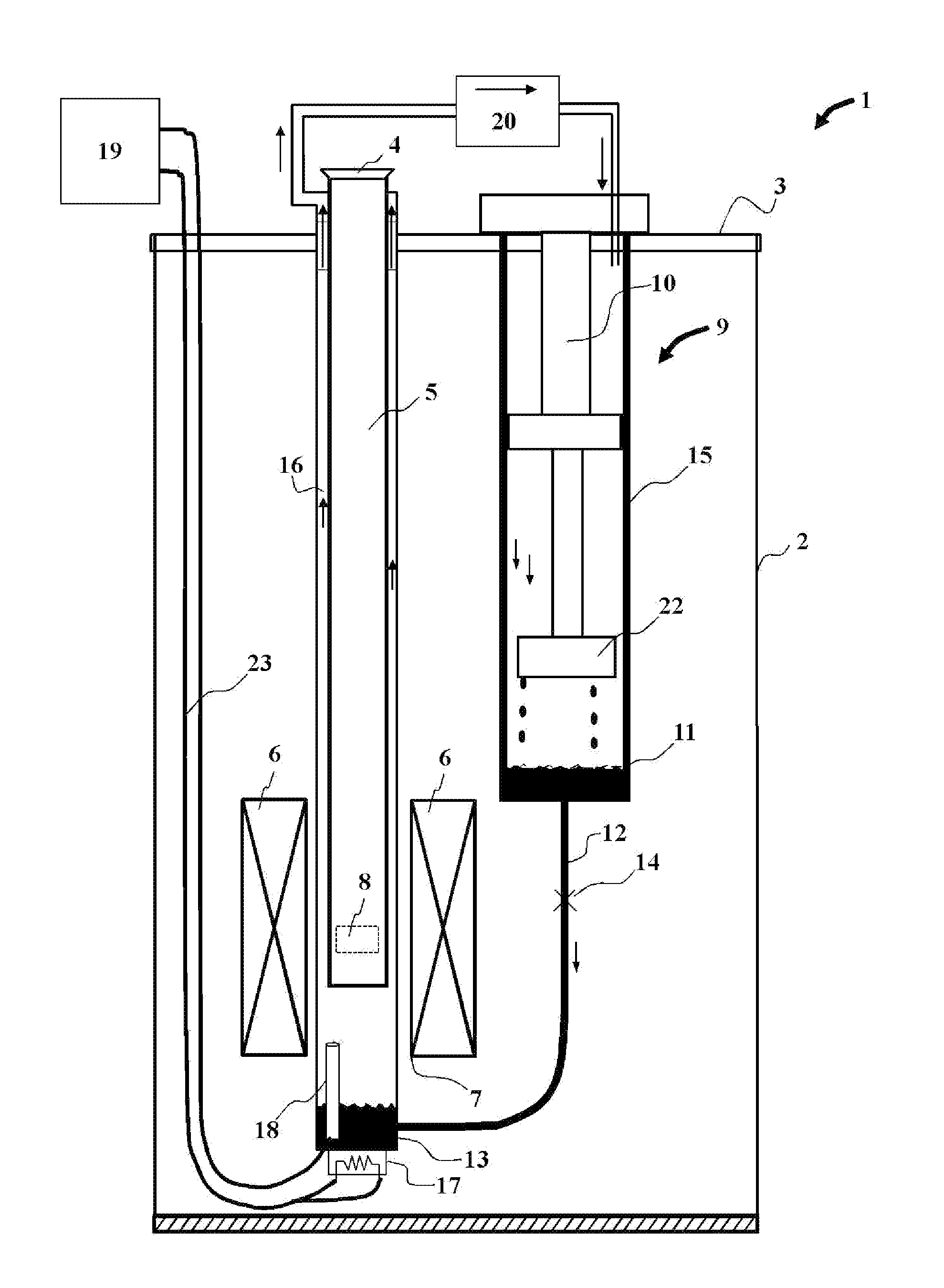
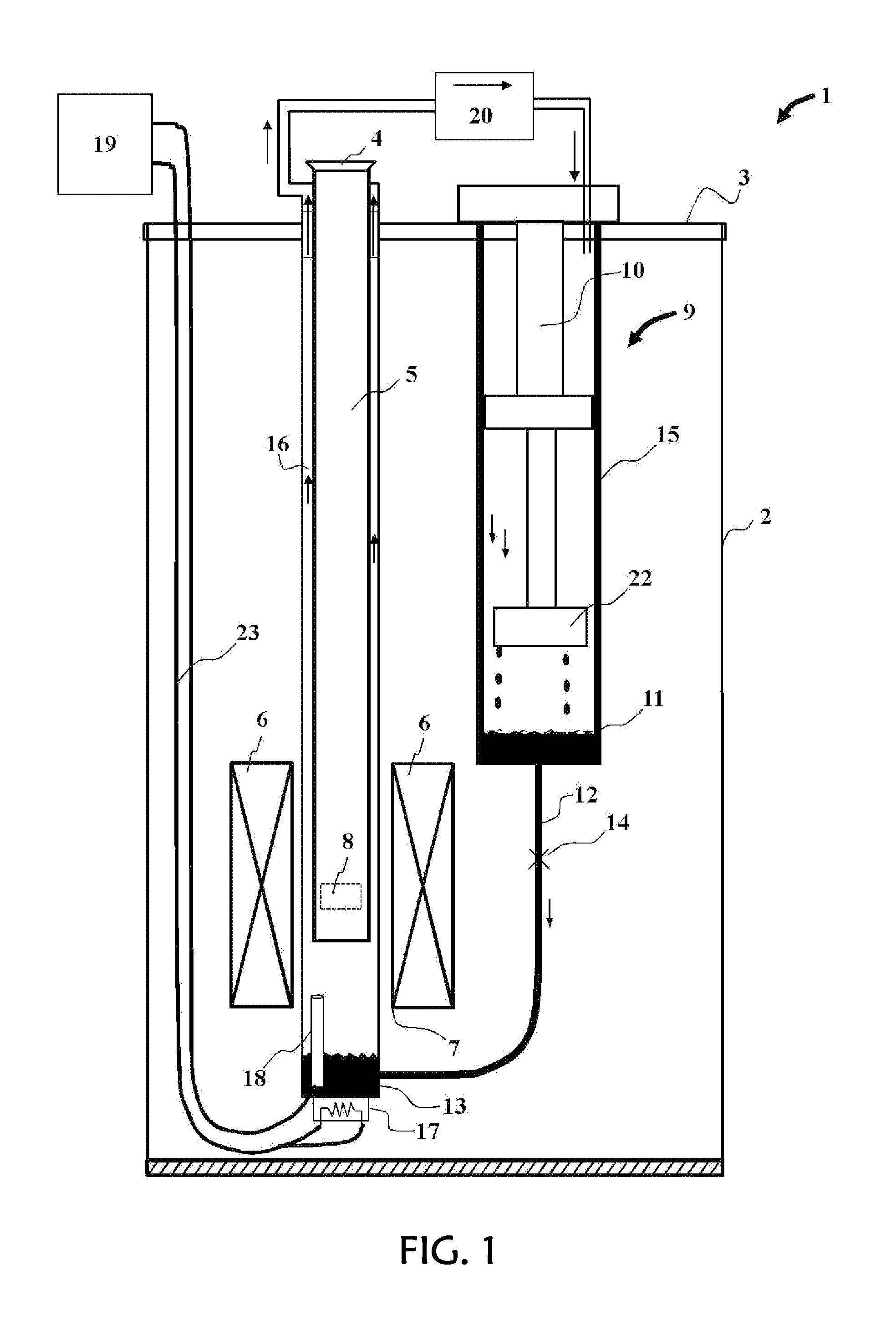
[0029]An exemplary embodiment of the apparatus of this invention is illustrated in FIG. 1, wherein a cryostat apparatus 1 comprises an outer vacuum chamber or outer shell 2 closed at the top by means of a top element or plate 3. While the shell 2 is shown as a distinct component from the top plate 3, in practice these two may be integral. The region outside this shell is usually at ambient temperature and pressure in air, while the volume inside this outer shell is evacuated so as to provide thermal isolation for, and between the various internal components. The top plate has openings for various penetrations into the interior of the cryostat, including a chamber access port 4 to provide access to the sample chamber 5.

[0030]Superconducting magnet 6 is shown with an inner bore 7 that houses the lower portion of the sample chamber, but is thermally isolated from it by virtue of the isolation vacuum. In this way, the temperature of the sample chamber may be varied independently from th...


PUM


Abstract

A gas-flow cryostat adapted for dynamic temperature regulation using a fluid level sensor; the cryostat further including one or more heaters coupled to various components of the cryostat. As fluid evaporates from a liquid coolant evaporation reservoir within the cryostat, the fluid level sensor and a feedback control unit are adapted to monitor and dynamically control the level of evaporating coolant by regulating the heaters. Accordingly, the cryostat is adapted to dynamically control temperature about a specimen region within the cryostat. The cryostat can be used in various applications, including analytical laboratory equipment for measuring various physical properties of samples. Temperature sensors are further incorporated for added control and optimization of the cryostat.

Description

CROSS-REFERENCE TO RELATED APPLICATIONS[0001]This application is a continuation of U.S. Ser. No. 12 / 797,556, filed Jun. 9, 2010; the entire contents of which are hereby incorporated by reference.FIELD OF THE INVENTION[0002]The present invention relates to cryostats, and methods for controlling the temperature of a region or sample within a cryostat; and more particularly to cryostats and related methods useful in measuring physical properties of samples over a wide temperature range.BACKGROUND OF THE INVENTION[0003]Cryogenic helium flow cryostats have been used for many years to regulate temperature in systems designed to test the physical properties of laboratory specimens. The need for testing physical specimens has increased substantially over the last several years. These systems are designed to characterize the physical properties of various materials under variable measurement conditions. Furthermore, these systems are capable of being programmed for an arbitrary sequence of t...

Claims


Application Information

Patent Timeline
Patent Type & Authority Applications(United States)
IPC IPC(8): F17C7/04F17C13/02F17C13/04F25D31/00
CPCF25B2400/01F25B2400/17G01F23/263F25D19/00F28F3/12F25B2700/04F17C3/085F17C13/006F17C2250/0408F17C2250/0417F17C2250/061F17C2250/0636
Inventor BLACK, RANDALLMARTIEN, DINESHNEILS, WILLIAM
Owner QUANTUM DESIGN
Why Eureka
Try Eureka