

Structure and manufacturing method for pressure vessel
a manufacturing method and pressure vessel technology, applied in the direction of vessel construction details, transportation and packaging, other domestic articles, etc., can solve the problems of difficult to form a resin containing fiber layer thickly, the burst pressure of the pressure vessel may not be improved as expected, and the lattice-shaped reinforcement layer cannot be easily formed three-dimensionally, so as to prevent the effect of improving the burst pressure of the pressure vessel
- Summary
- Abstract
- Description
- Claims
- Application Information
AI Technical Summary
Benefits of technology
Problems solved by technology
Method used
Image

Examples
first embodiment
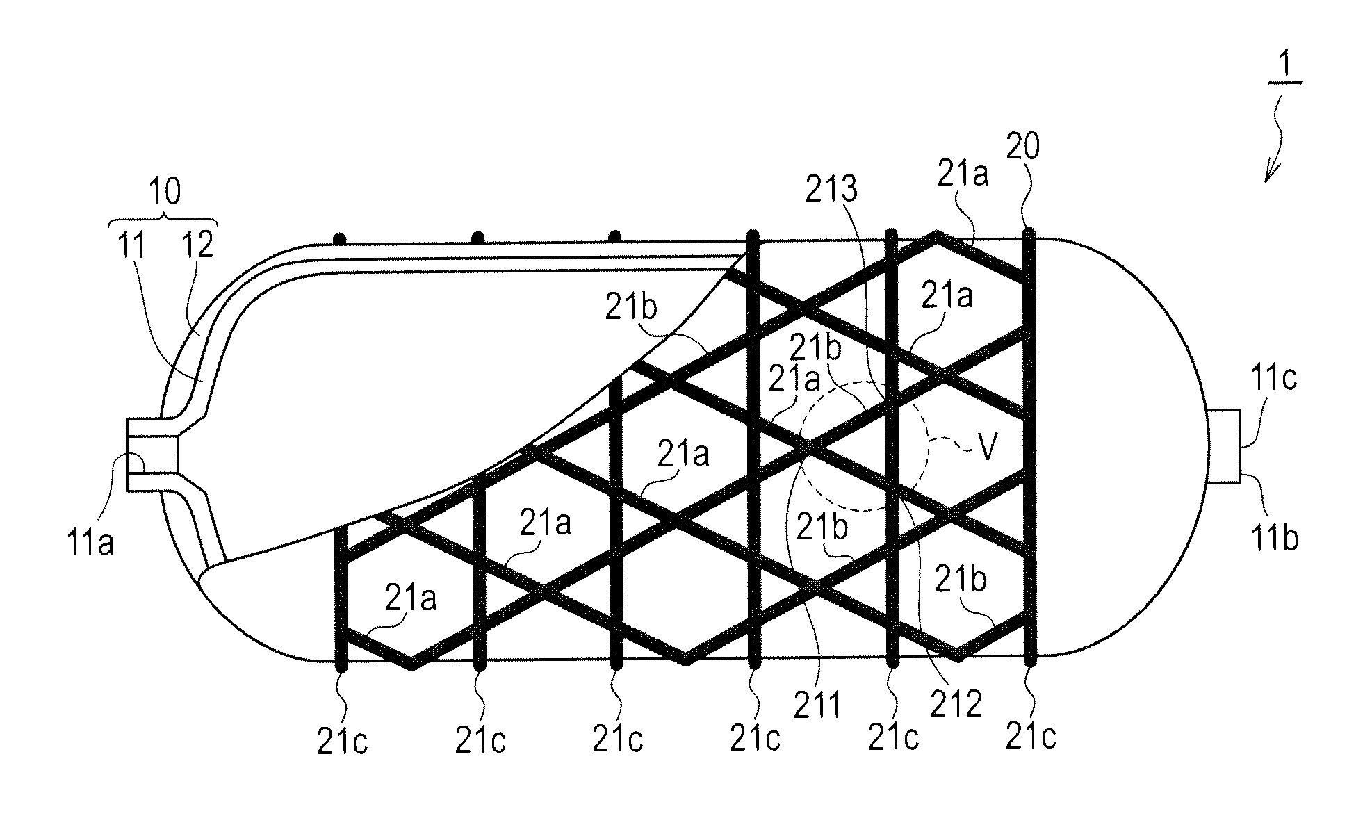
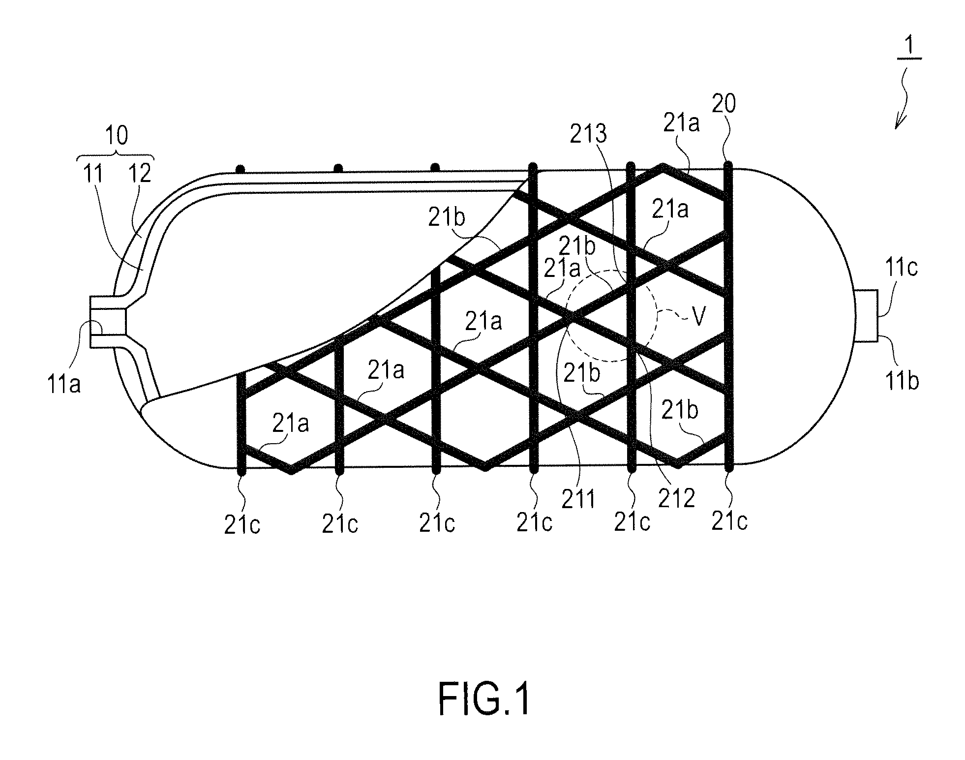
[0024]FIG. 1 is a view showing a first embodiment of a pressure vessel structure according to this invention.
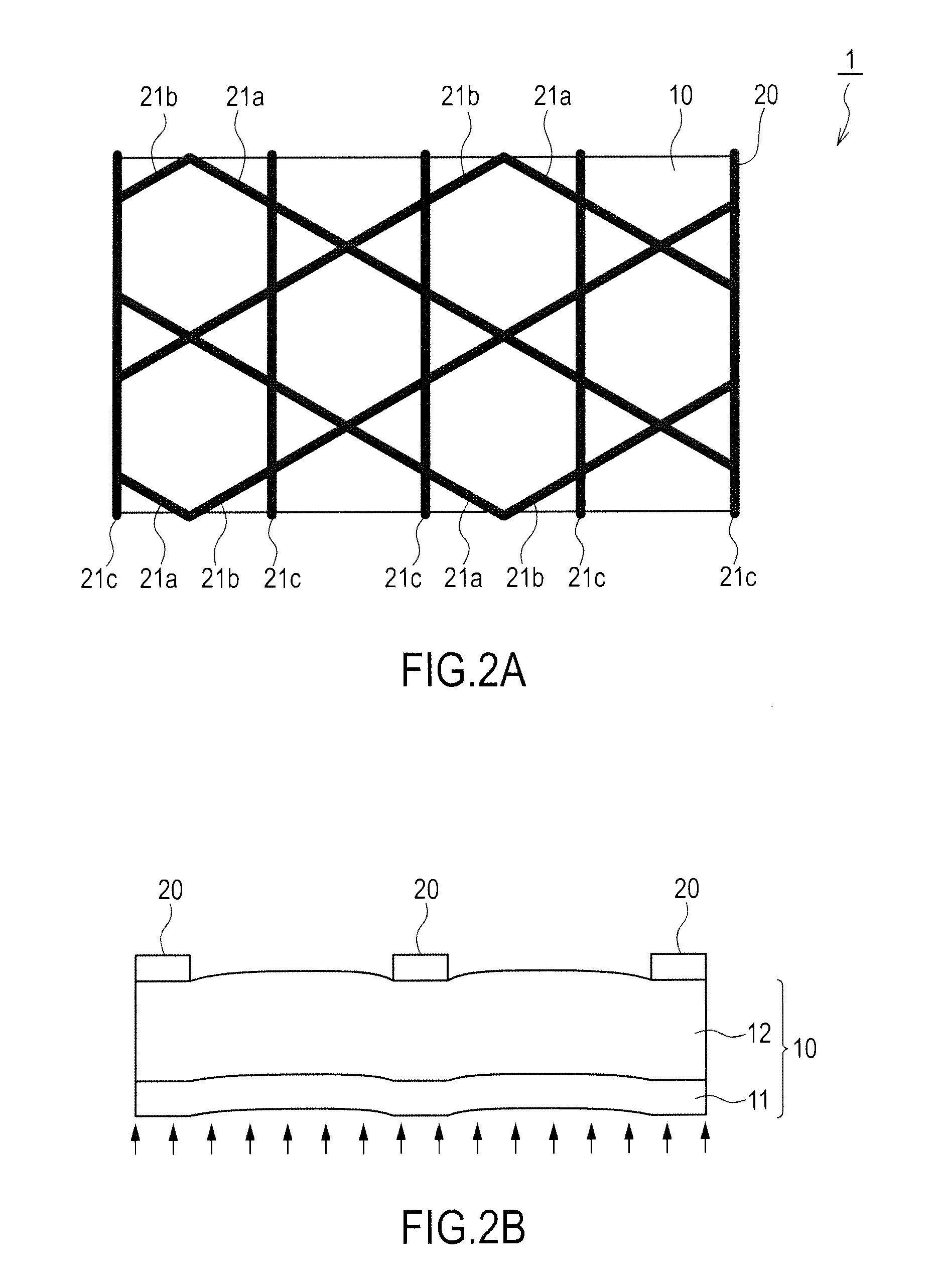
[0025]A pressure vessel 1 includes a vessel main body 10 and a grid layer 20.
[0026]The vessel main body 10 includes a liner 11 and a fiber reinforced plastic (FRP) layer 12.
[0027]The liner 11 is a gas storage body, the interior of which serves as a gas storage space. Liquid fuel may be stored in the storage space at normal pressure, and fuel gas may be stored in the storage space at a higher pressure than normal pressure. When the pressure vessel is used to store hydrogen gas for a fuel cell automobile, hydrogen gas is stored in the storage space at a high pressure of 35 MPa or 70 MPa, for example. It should be noted that a temperature of the liner 11 varies in accordance with a peripheral temperature, during charging and discharging of the hydrogen gas, and so on, and a variation width thereof differs according to the pressure of the hydrogen gas. The liner 11 is formed usin...
second embodiment
[0067]FIG. 7 is a sectional view showing a second embodiment of the pressure vessel structure according to this invention.
[0068]In this embodiment, the vessel main body 10 is formed by providing the fiber layer 13 on the surface of a pre-existing vessel main body in which the pre-existing fiber reinforced plastic layer 12 is formed on the liner 11. In so doing, there is substantially no need to modify a conventionally employed manufacturing line, and therefore an increase in manufacturing cost can be suppressed.
[0069]Further, in this embodiment, the fiber layer 13 is formed by providing the helically wound resin containing fiber 13a formed in an orthogonal fiber direction to the first helically wound grid lines 21a of the grid layer 20, the helically wound resin containing fiber 13b formed in an orthogonal fiber direction to the second helically wound grid lines 21b, and the helically wound resin containing fiber 13c formed in an orthogonal fiber direction to the hoop wound grid lin...
third embodiment
[0070]FIG. 8 is a sectional view showing a third embodiment of the pressure vessel structure according to this invention.
[0071]In this embodiment, the vessel main body 10 is manufactured by forming the fiber layer 13-1 on the surface of the liner 11, forming the pre-existing fiber reinforced plastic layer 12 thereon, and forming the fiber layer 13-2 thereon. It should be noted that this structure is similar to the structure used in the burst pressure experiment, shown in FIG. 3C.
[0072]The bending stress acting on the vessel main body 10 is greatest on an outermost layer and an innermost layer relative to a neutral plane. This bending stress can be alleviated by the fiber layer 13-1 provided on the innermost layer of the fiber reinforced plastic layer 12 and the fiber layer 13-2 provided on the outermost layer, and therefore impairment of an improvement in the burst pressure of the pressure vessel can be prevented even more effectively.
PUM
| Property | Measurement | Unit |
|---|---|---|
| pressure | aaaaa | aaaaa |
| pressure | aaaaa | aaaaa |
| burst pressure | aaaaa | aaaaa |
Abstract
Description
Claims
Application Information