Magnetic resonance imaging with improved imaging contrast

a magnetic resonance imaging and contrast technology, applied in the field of magnetic resonance imaging of objects, can solve the problems of data inconsistency and image artifacts, limits the implementation of high-resolution epi techniques, and the resolution is typically limited to more than a millimeter for humans, so as to reduce the unwanted influence of t2* relaxation, minimize the echo time, and maximize the snr

Inactive Publication Date: 2012-01-19
MAX PLANCK GESELLSCHAFT ZUR FOERDERUNG DER WISSENSCHAFTEN EV
View PDF7 Cites 72 Cited by
  • Summary
  • Abstract
  • Description
  • Claims
  • Application Information

AI Technical Summary

Benefits of technology

[0055]According to a further important advantage of the invention, collecting the time-dependent image sequence can be utilized for providing a three-dimensional (3D) reconstruction of the object. The steps of k-space sampling in the two segments, i.e. the pairwise segment sampling is conducted with a changing direction of the phase blips relative to an axis deviating from the axis of phase encoding. Thus, the 3D reconstruction of the object is obtained with a cylindrical 3D sampling geometry. The phase blips are rotated by a predetermined rotation angle (φ), preferably about the readout direction, for each of the two segments of k-space sampling steps. Typically, the phase blips can be gradually rotated by the rotation angle for each of the sampling steps. Alternatively, the rotation angle (φ) of the direction of the phase blips can be selected with a randomized or pseudo-randomized acquisition scheme.
[0056]According to a particularly preferred embodiment of the invention, a preparation step is provided before the k-space sampling. Advantageously, the preparation step creates a magnetic preconditioning of the object for facilitating a predetermined magnetic spin concentration contrast to be imaged. A general advantage of including the preparation step to the DEPICTING method is the achievement of a minimal echo time, which maximizes the SNR, reduces unwanted influences from T2* relaxation on the image contrast, and minimizes the time for evolution of phase errors due to magnetic field inhomogeneities.
[0057]The preparation step includes subjecting the object to at least one RF preparation pulse. Subsequently, the inventive k-space sampling is conducted. The at least one RF preparation pulse can be created before each pair of two excitations pulses with subsequent encoding sequences. Alternatively, the at least one RF preparation pulse can once be created for all subsequent encoding sequences. The k-space sampling is conducted after a predetermined magnetization recovery delay time (Tdelay) relative to the end of the at least one preparation pulse. The recovery delay time is selected in dependence on the type of preparation and the contrast to be enhanced by the preparation. During the magnetization recovery delay time, the object can be subjected to spoiling gradients, again selected in dependence on the type of preparation and the contrast to be enhanced.
[0058]The at least one RF preparation pulse may comprise a single 180° inversion pulse, a composite inversion pulse, an adiabatic inversion pulse, a sequence of RF inversion pulses designed to achieve inversion of the magnetization, or a sequence of RF pulses designed to achieve rotating the magnetization by 90° and to achieve saturation.
[0059]If the object is subjected to a driven-equilibrium pulse sequence before each or all of the excitation and encoding sequences of magnetic field gradients, image contrast can be generated which depends upon the transverse relaxation time, T2. The traditional driven-equilibrium pulse sequence of the preparation step may also be modified to produce a stimulated echo instead of a primary spin echo. According to a further variant of the driven-equilibrium pulse sequence, a pair of identical diffusion-weighting gradient lobes can be added on either side of the refocusing pulse or sequence of refocusing pulses of the driven-equilibrium pulse sequence. Thus, a diffusion-weighted DEPICTING pulse sequence can be obtained.
[0060]The preparation step can be utilized for spectroscopic DEPICTING imaging. To this end, the object is subjected to a combination of two 90° pulses or another sequence of RF pulses designed to achieve rotating the magnetization by 90° followed by a variable evolution period t1 for encoding of the resonance frequency and rotating the magnetization back to the longitudinal axis. Subsequently, the object is subjected to spoiling gradients following the rotating RF pulses.

Problems solved by technology

On the other hand, EPI is also prone to a variety of image artifacts (e.g., Nyquist ghosting, chemical shift displacements, distortions and signal voids arising from magnetic susceptibility variations across the object, image blurring due to effective transverse relaxation during the EPI readout), and the resolution is typically limited to more than a millimeter for human applications [2, 3].
Unless T2* relaxation is the wanted contrast mechanism, as for example in functional brain mapping based on the blood oxygen level dependent (BOLD) effect, this intrinsic signal loss causes problems in the application of EPI for anatomical imaging and seriously limits the implementation of high-resolution EPI techniques.
The major problem is that different phase errors are contained in each tile leading to data inconsistency and image artifacts.
The lack of sufficient robustness has so far limited the routine use of mosaic EPI [3, 11].
In previous applications, however, the accuracy of the field-mapping scan was rather low [15, 16] or distortions were even completely ignored [14], which only permits imaging at rather low resolution.

Method used


Image

  • Magnetic resonance imaging with improved imaging contrast
  • Magnetic resonance imaging with improved imaging contrast
  • Magnetic resonance imaging with improved imaging contrast

Examples


Embodiment Construction

[0076]Preferred embodiments of the invention are described in the following with particular reference to the construction of the excitation and encoding sequences. Timing sequences are graphically represented as introduced in prior publications, see e.g. publications [5] and [20]. Details of creating the RF pulses and gradients of these sequences, collecting the MR signals and controlling an MR scanner as well as details of the construction of an MR scanner are not described as far as they are known from conventional MR imaging techniques. Furthermore, after reconstructing the at least one image of the object, the image can be subjected to a further image processing or image recording, displaying, storing, or printing as it is known in prior art.

DEPICTING Method

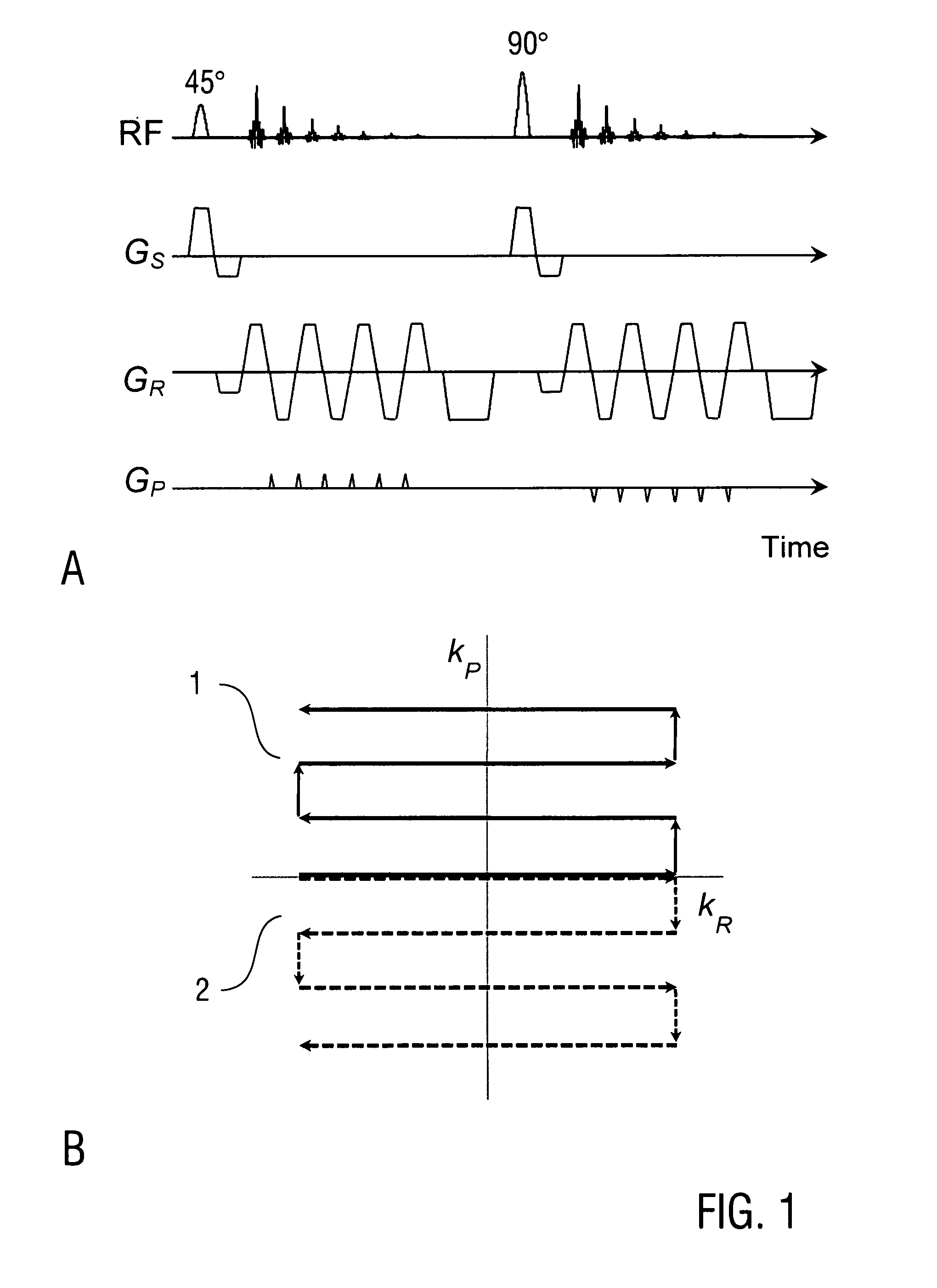
[0077]FIG. 1 shows the basic RF pulse and gradient sequence for the inventive DEPICTING method and the corresponding k-space trajectories. The first tile 1 of k-space data is sampled with a given polarity of the phase blips (...


PUM


Abstract

A method of magnetic resonance imaging of an object comprises the steps of arranging the object in a stationary magnetic field, subjecting the object to an excitation and encoding sequence of magnetic field gradients resulting in k-space sampling in two segments along the phase encoding direction, wherein the encoding sequence of the magnetic field gradients is selected such that the two segments in k-space are sampled along trajectories beginning with a central k-space line through the k-space center and continuing to opposite k-space borders of the two segments, collecting magnetic resonance signals created in the object, and reconstructing an image of the object based on the magnetic resonance signals, wherein one central k-space line is sampled in both of the two k-space segments, and intersegment phase and / or intensity deviations are corrected in both k-space segments using the magnetic resonance signals collected along the central k-space line. Furthermore, an imaging device for magnetic resonance imaging of an object is described.

Description

TECHNICAL FIELD[0001]The present invention relates to a method of magnetic resonance (MR) imaging of an object, in particular to an MR imaging (MRI) method with improved imaging contrast and / or shortened acquisition time. Furthermore, the invention relates to an MRI device adapted for implementing the MRI method. Preferred applications of the invention are in the field of biomedical MRI.TECHNICAL BACKGROUND OF THE INVENTION[0002]In the present specification, reference is made to the following publications cited for illustrating prior art techniques and conventional implementations of certain procedural measures or partial aspects of excitation and encoding sequences.[0003][1] P. Mansfield. Multi-planar image formation using NMR spin echoes. J. Phys. C: Solid State Phys. 10: L55-L58 (1977).[0004][2] H. Fischer, R. Ladebeck. Echo planar imaging image artifacts. In: F. Schmitt, M. K. Stehling, R. Turner, eds. Echo-Planar Imaging: Theory, Technique and Application. Springer, Berlin (199...

Claims


Application Information

Patent Timeline
Patent Type & Authority Applications(United States)
IPC IPC(8): G01R33/54G01R33/28
CPCG01R33/4806G01R33/4818G01R33/482G01R33/4828G01R33/483G01R33/485G01R33/56563G01R33/5616G01R33/56341G01R33/56366G01R33/56536G01R33/56554G01R33/5607
Inventor HETZER, STEFANMILDNER, TORALFMOELLER, HARALD
Owner MAX PLANCK GESELLSCHAFT ZUR FOERDERUNG DER WISSENSCHAFTEN EV
Why Eureka
Try Eureka