Startup circuit

a technology of start-up circuit and discharge resistor, which is applied in the direction of dc-dc conversion, power conversion system, electrical apparatus, etc., can solve the problems of power loss and power consumption of discharge resistors that are not ignorable, and achieve the effect of preventing electric shock

Inactive Publication Date: 2012-01-19
SANKEN ELECTRIC CO LTD
View PDF10 Cites 21 Cited by
  • Summary
  • Abstract
  • Description
  • Claims
  • Application Information

AI Technical Summary

Benefits of technology

[0015]In the switching power source apparatus of FIG. 1, the discharge resistor R0 connected between AC lines of an AC plug connected to the AC power source AC generally has a resistance of about 2 MΩ, although the value is dependent on the capacitance of the capacitor C0 serving as an EMI (electromagnetic interference) filter. When the AC plug is removed from an AC plug of the AC power source AC, the capacitor C0 is discharged through the discharge resistor R0, to prevent an electric shock.
[0022]The present invention provides a startup circuit capable of eliminating a discharge resistor connected between AC lines of an AC plug and reducing power consumption during a standby state.

Problems solved by technology

If the discharge resistor R0 connected between the AC lines of the AC plug is of 2 MΩ, the resistance of 2 MΩ always consumes power to cause a power loss.
Such regulations will become severer in the future, and therefore, power consumption by the discharge resistor is not ignorable.

Method used


Image

  • Startup circuit
  • Startup circuit
  • Startup circuit

Examples


embodiment 1

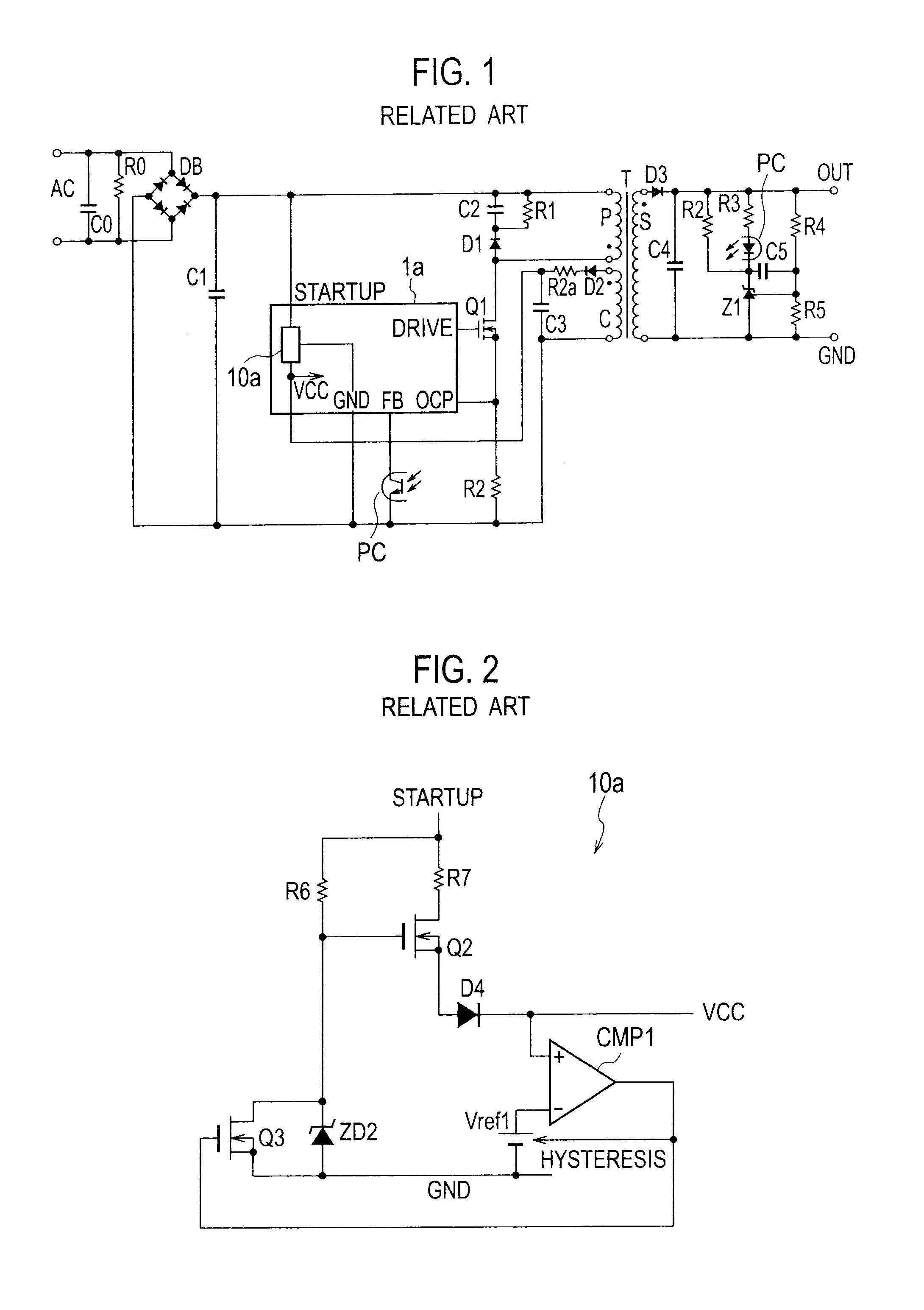
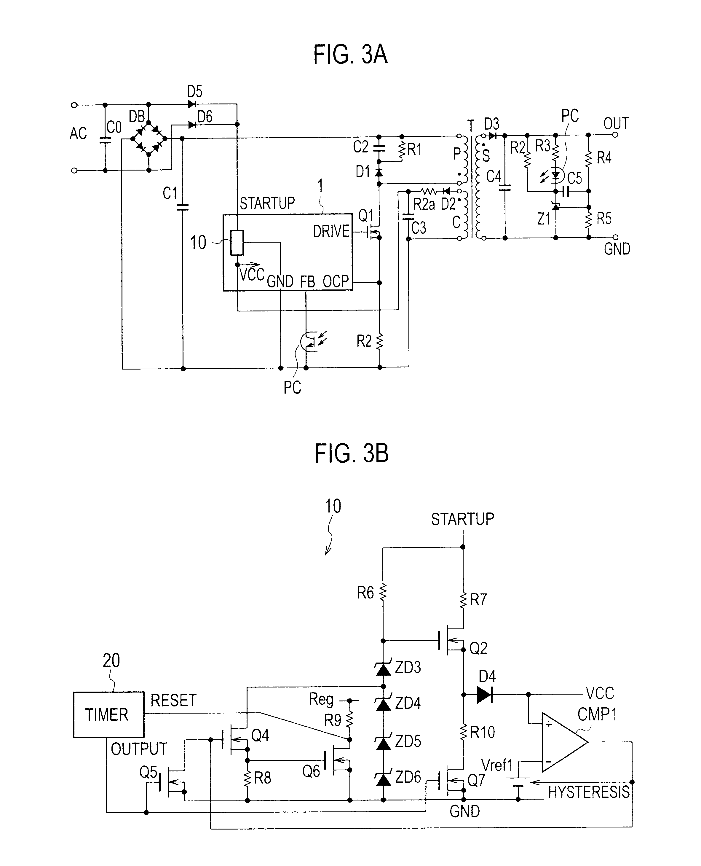
[0032]FIG. 3A is a circuit diagram illustrating a switching power source apparatus including a startup circuit according to Embodiment 1 of the present invention and FIG. 3B is a circuit diagram illustrating the startup circuit. The switching power source apparatus includes a controller 1 incorporating the startup circuit 10. In the switching power source apparatus, a first end of a capacitor C0 is connected to an anode of a diode D5, a cathode of the diode D5 is connected to a terminal STARTUP of the controller 1, a second end of the capacitor C0 is connected to an anode of a diode D6, and a cathode of the diode D6 is connected to the terminal STARTUP.

[0033]The remaining configuration of FIG. 3A is the same as that of FIG. 1, and therefore, like parts are represented with like reference marks to omit a repetition of explanation.

[0034]The controller 1 of FIG. 3A has the same terminals as the controller 1a of FIG. 1 and is different therefrom in that the controller 1 has the startup ...

embodiment 2

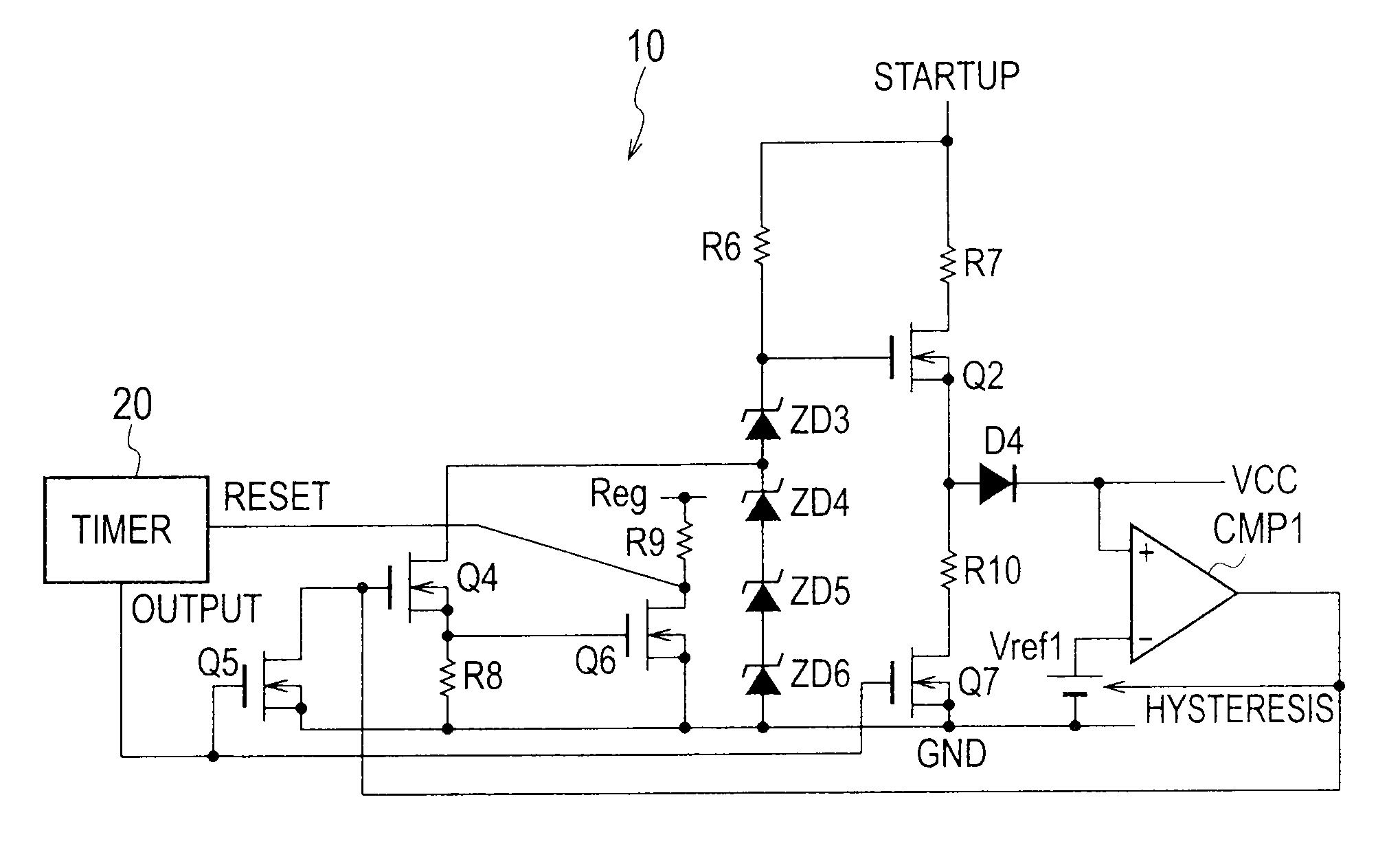
[0054]FIG. 5 is a circuit diagram illustrating a startup circuit according to Embodiment 2 of the present invention. Like the startup circuit 10 of Embodiment 1, the startup circuit 11 of Embodiment 2 is incorporated in the controller 1 illustrated in FIG. 3A. The startup circuit 11 according to Embodiment 2 is characterized in that it resets a timer 20 according to a voltage at the terminal STARTUP.

[0055]In the startup circuit 11 of FIG. 5, first ends of resistors R6, R7, and R11 are connected to the terminal STARTUP. A second end of the resistor R6 is connected to a cathode of a zener diode ZD7. The zener diode ZD7 has a zener voltage of, for example, 28 V.

[0056]A second end of the resistor R7 is connected to a drain of a switch element Q2. A source of the switch element Q2 is connected to a first end of a resistor R10 and an anode of a diode D4. A cathode of the diode D4 is connected to the terminal VCC and a non-inverting input terminal of a hysteresis comparator CMP1. An invert...


PUM


Abstract

A startup circuit is installed in a switching power source apparatus. The startup circuit is configured to start up a controller with the use of a rectified voltage at startup of an AC power source and includes a detector (ZD3, Q4, Q6) to detect if the rectified voltage is equal to or lower than a predetermined voltage, a timer 20 to count a predetermined time after the rectified voltage is detected to be equal to or lower than the predetermined voltage, and a discharger (R10, Q7) to discharge the rectified voltage if the rectified voltage does not become equal to or lower than a specified voltage within the predetermined time counted by the timer.

Description

BACKGROUND OF THE INVENTION[0001]1. Field of the Invention[0002]The present invention relates to a startup circuit installed in a switching power source apparatus, to reduce power consumption in a standby mode such as a waiting mode of a remote control command.[0003]2. Description of Related Art[0004]FIG. 1 is a circuit diagram illustrating a switching power source apparatus incorporating a startup circuit according to a related art. In FIG. 1, both ends of an AC power source AC are connected to a capacitor C0, a discharge resistor R0, and input ends of a full-wave rectifier DB. Output ends of the full-wave rectifier DB are connected to a smoothing capacitor C1 and a series circuit that includes a primary winding P of a transformer T, a switch element Q1 made of a MOSFET, and a resistor R2. Both ends of the primary winding P are connected to a series circuit that includes a capacitor C2 and a diode D1. Both ends of the capacitor C2 are connected to a resistor R1.[0005]Both ends of a...

Claims


Application Information

Patent Timeline
Patent Type & Authority Applications(United States)
IPC IPC(8): H02M7/02
CPCH02M3/33507H02M1/36H02M1/322
Inventor KOIKE, KENGO
Owner SANKEN ELECTRIC CO LTD
Why Eureka
Try Eureka