
Reactor head seismic support tie rod system

a technology of seismic support and reactor head, which is applied in the direction of nuclear engineering, nuclear elements, greenhouse gas reduction, etc., can solve the problems of radiation exposure, affecting the overall refueling time, etc., and achieve the effect of facilitating alignment over the dowel pin portions

Active Publication Date: 2012-01-19
WESTINGHOUSE ELECTRIC CORP
View PDF9 Cites 19 Cited by
  • Summary
  • Abstract
  • Description
  • Claims
  • Application Information

AI Technical Summary

Benefits of technology

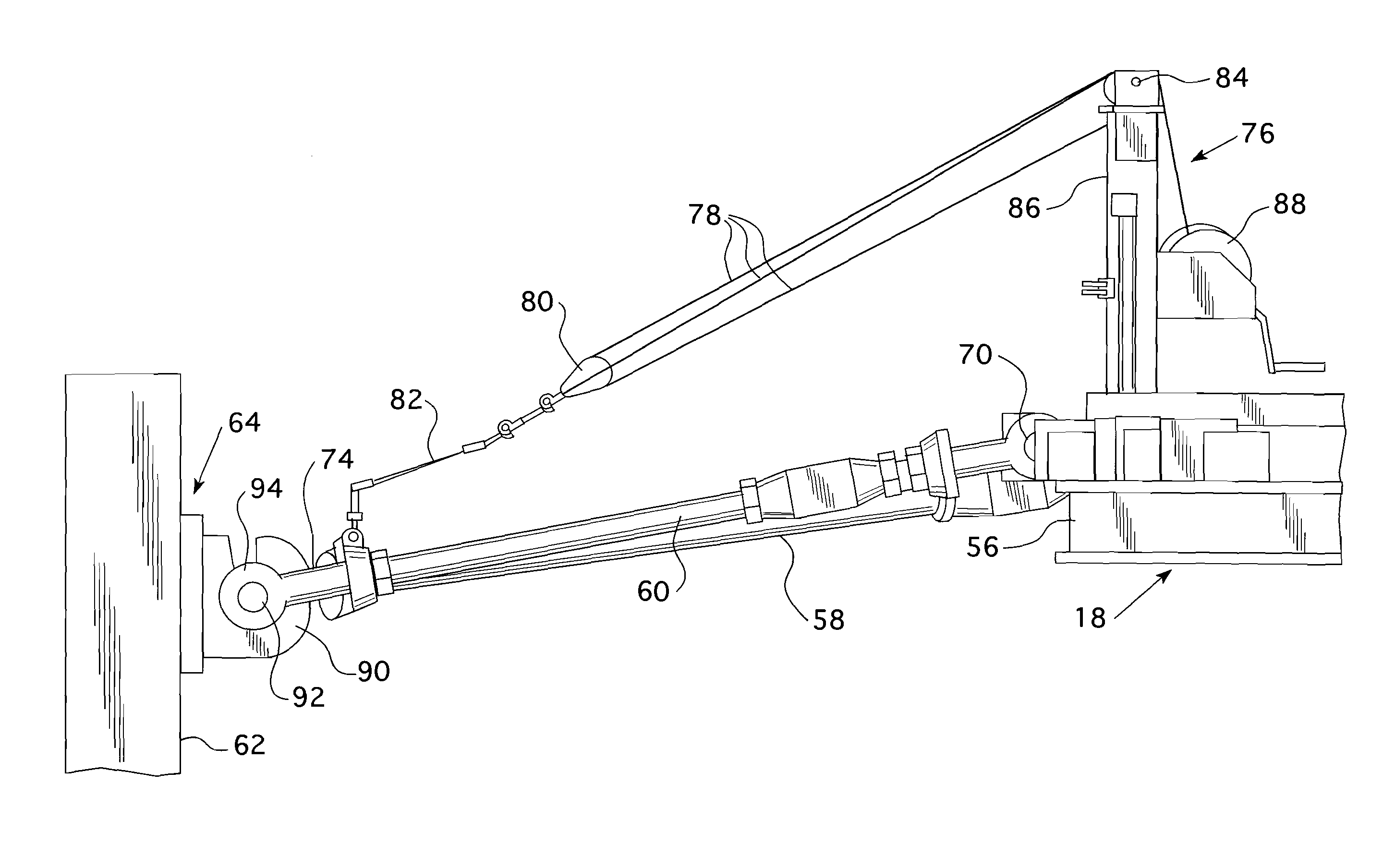
[0014]In still another embodiment wherein the anchor includes a plate that extends generally toward the reactor vessel, substantially in line with the corresponding tie rod that it connects with, the anchor has a first dowel portion extending laterally from one side of the plate and a second dowel portion extending from an opposite side of the plate. The adjacent end of the tie rod is formed to slip over and engage the first and second dowel portions from above when the tie rods are pivoted down at the reactor vessel head assembly. The plate has a locking bar that is operable from a remote location on an operating deck of the containment to move over the tie rod end when the tie rod end fully engages the first and second dowel portions to lock the tie rod end to the anchor. Preferably, the tie rod end is configured as a fork with two tines spaced to receive the plate therebetween. Each of the tines has a downward facing clevis opening that receives a corresponding dowel portion as the tie rod is pivoted downward over the plate. Desirably, a locking bar is operable from the remote location on the operating deck to rotate between an open position wherein the locking bar lies over the top of the plate, clear of the tines of the tie rod end and a closed position, approximately 90 degrees from the open position, where the locking bar lies over each of the tines. The locking bar is preferably rotated by a long-handled tool that has a forked lower end that grips an upwardly extending wall on the locking bar. Desirably, the locking bar can be latched in either or both the open or closed position. Preferably, the clevis opening in the tie rod end has a taper at a lower end of at least one wall of the clevis opening slot to facilitate alignment over the dowel pin portions.

Problems solved by technology

Such operations affect overall refueling time and radiation exposure and require space in the containment area for placement of the missile shield slabs when removed from the position above the reactor vessel.

Method used


Image

  • Reactor head seismic support tie rod system
  • Reactor head seismic support tie rod system
  • Reactor head seismic support tie rod system

Examples


Embodiment Construction

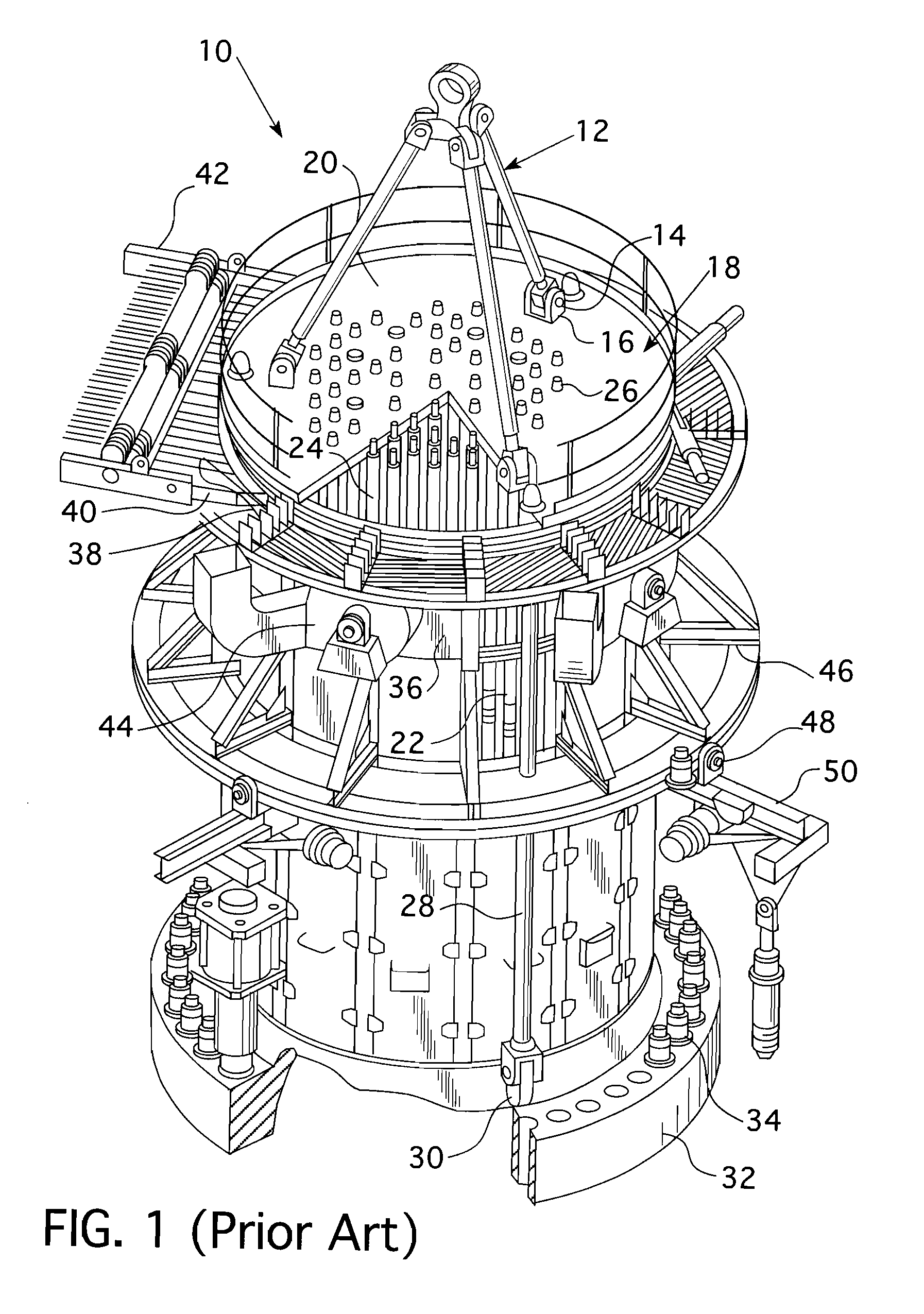
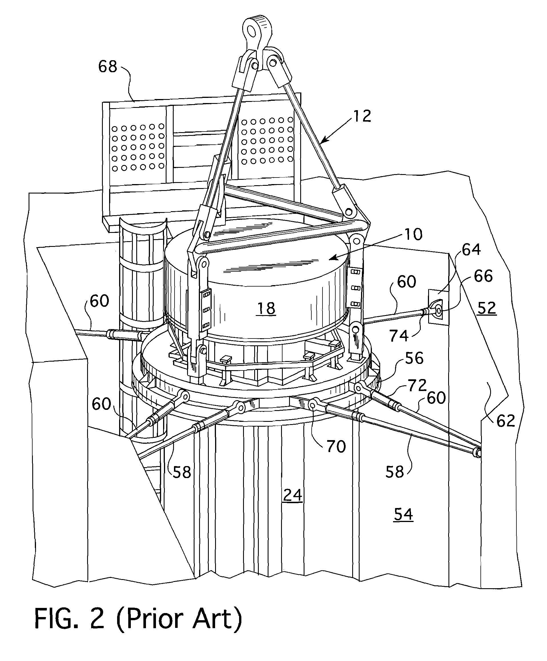
[0031]FIG. 2 shows a perspective view of the portion of the operating deck 52 which surrounds the reactor vessel cavity 54 and a portion of the integrated head package 10 showing a missile shield 18 seated over the control rod travel housing extensions 24 and coupled to the lifting rig 12 that was previously described with respect to FIG. 1. The integrated head package also includes a seismic ring 56 that is secured around the control rod travel housing extensions 24 and is secured against lateral movement by the tie rods 58 and 60 which are connected between the seismic ring 56 and the vessel cavity wall 62. As can be seen from plan view in FIG. 3 of this prior art arrangement, six tie rods, four radial tie rods 60 and two tangential tie rods 58 secure the control rod travel housing extensions 24 from lateral movement. The tie rods are connected at one end 72 to the seismic ring 56 on the integrated head package 10 through a pinned coupling 70 and are connected at another end 74 to...


PUM


Abstract

A quick disconnect for a control rod drive mechanism seismic support tie rod system that is remotely operable from a nuclear power plant's operating deck. A wall mounted anchor in the reactor cavity contains one half of a disconnect coupling that interfaces with the other half of the disconnect coupling on the ends of the tie rods employing a remote winching system that is actuated from the top of the reactor head assembly. A latching mechanism is then actuated from the refueling cavity operating deck to lock the tie rod in place and prevent displacement during a seismic or pipe break event. The tie rod may similarly be unlocked from the wall anchor and raised above the reactor head assembly as part of a reactor head disassembly operation to gain access to the core of the reactor vessel for refueling.

Description

BACKGROUND OF THE INVENTION[0001]1. Field of the Invention[0002]This invention pertains generally to control rod drive mechanism seismic supports for nuclear power plants and more particularly to a quick disconnect seismic support tie rod system.[0003]2. Description of the Related Art[0004]In conventional reactors, the head package includes the pressure vessel head which seals the reactor vessel, control rod drive mechanisms which are used to raise and lower control rods in the core of the reactor, a seismic platform adjacent the upper ends of the control rod drive mechanisms, which laterally restrains the drive mechanisms, and various cables for operation of the control rod drive mechanisms. A missile shield, which conventionally was formed of a concrete slab, is positioned above the head package to protect the containment housing and associated equipment from penetration by any of the control rod drive mechanisms in the event of a major pipe break. The problems associated with suc...

Claims


Application Information

Patent Timeline
Patent Type & Authority Applications(United States)
IPC IPC(8): G21C19/00G21C9/00
CPCG21C9/00G21C19/00G21C13/024Y02E30/40G21D1/02Y02E30/30Y02E30/00G21C19/10
Inventor FRANK, COURTNEY B.CONRAD, MICHAEL D.HIMLER, JEFFREY C.ERDMAN, DANIEL J.HEINZ CARNICELLI, MICHELLE
Owner WESTINGHOUSE ELECTRIC CORP
Learn More