Method for producing a HTS coated conductor and HTS coated conductor with reduced losses

a technology of hts coated conductors and hts coated conductors, which is applied in the direction of superconductors/hyperconductors, superconductors/coils, magnetic bodies, etc., can solve the problems of low temperature superconductors (typically used in this area) reducing the critical current and critical magnetic field, electrical losses, and insufficient current performance of low temperature superconductors. achieve the effect of high efficiency in the area

Active Publication Date: 2012-01-19
BRUKER HTS
View PDF0 Cites 7 Cited by
  • Summary
  • Abstract
  • Description
  • Claims
  • Application Information

AI Technical Summary

Benefits of technology

[0032]Particularly advantageous is a variant wherein step a) is performed such that the roughened surface has a one- or two-dimensional periodicity. In other words, in step a), roughening structures are provided with a one- or two-dimensional periodicity. The periodicity of the roughened surface results in a periodic arrangement of the flux pipes during operation, allowing a highly efficient use of the area of the HTS coated conductor when distributing the flux pipes, and thus leading to particularly high critical currents and critical magnetic fields. Note that when applying/depositing further roughe

Problems solved by technology

This performance is important for high field magnets used in e.g. NMR where fields are so high that the current performance of low temperature superconductors (typically used in this area) becomes insufficient.
This redistribution or movement of the flux pipes causes electrical losses, and may decrease the critical current and the critical magnetic field of the HTS coated conductor at which the HTS materia

Method used


Image

  • Method for producing a HTS coated conductor and HTS coated conductor with reduced losses
  • Method for producing a HTS coated conductor and HTS coated conductor with reduced losses
  • Method for producing a HTS coated conductor and HTS coated conductor with reduced losses

Examples


second embodiment

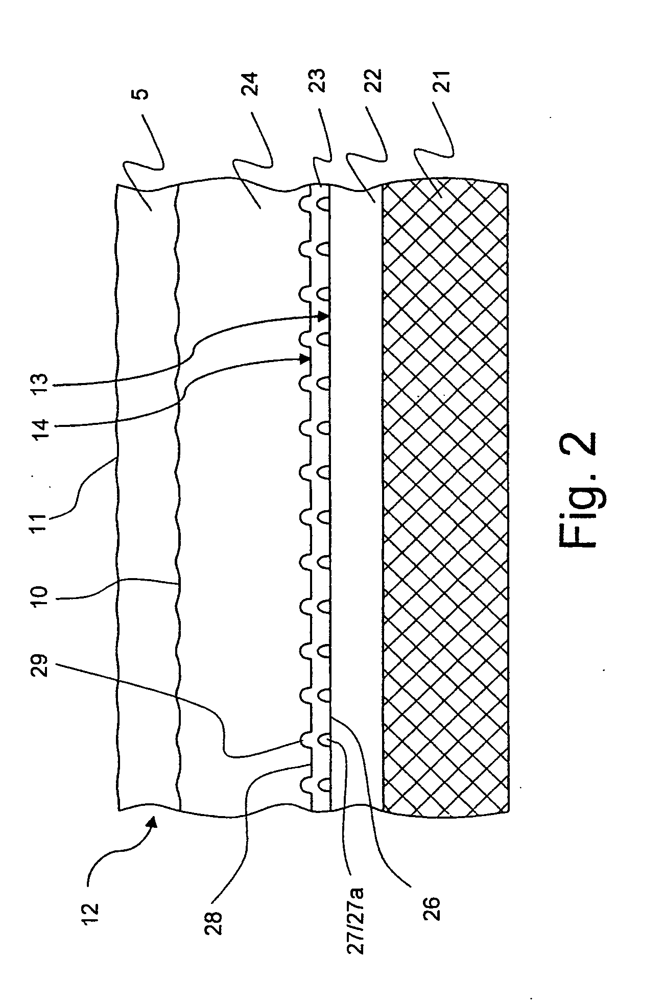
[0062]FIG. 2 shows an inventive HTS coated conductor 12. For simplification, only the differences as compared to FIG. 1 are explained in detail.

[0063]On the basically flat substrate 21, a basically flat buffer layer 22 has been deposited. In order to obtain a roughened surface 13, roughening structures 27 of local deposit type (here resembling islands or humps) have been placed on the buffer layer surface. The material of the local deposits 27a is Pt, for example, deposited via vacuum cluster deposition technique using a Knudsen evaporation cell. Between the local deposits 27a, flat surface area 26 remains.

[0064]On top of the roughened surface 13 (including the local deposits 27a), a closed intermediate layer 23 has been deposited. Its surface 14 imitates the roughened surface 13, exhibiting hump like reproduced roughening structures 29 and reproduced flat areas 28. Note that the aspect ratio of the reproduced roughening structures 29 is somewhat lower as compared to the roughening ...

third embodiment

[0070]FIG. 4 shows an inventive HTS coated conductor 12. Only the major differences with respect to FIG. 2 are discussed, for simplicity.

[0071]The substrate 21, the buffer layer 22, the roughening structures 27 and the intermediate layer 23 correspond to the embodiment shown in FIG. 2. However, the HTS layer 65, which is deposited on top of the intermediate layer 23, has been roughened, resulting in a further roughened surface 15. The roughening of the further roughened surface 15 has been done by depositing material on top of the HTS layer 65, i.e. further roughening structures 66 have been provided, here formed as further local deposits 66a on the surface of the HTS layer 65. It should be noted that the surface of the HTS layer 65 is somewhat wavy anyway, due to the roughened surface 13 (see slightly curved areas 73 between the roughening structures 66), but not wavy enough to guarantee flux pinning above, therefore the roughening was repeated.

[0072]A closed further intermediate l...


PUM


Abstract

A method for producing a high temperature superconductor (=HTS) coated conductor (12), wherein a buffer layer (2; 22) and an HTS layer (4; 24; 65) are deposited on a substrate (1; 21), with the following steps: a) after depositing the buffer layer (2; 22), the surface (2a) is locally roughened, resulting in a roughened surface (13), b) a non-superconducting, closed intermediate layer (3; 23) is deposited on top of the roughened surface (13), c) and the HTS layer (4; 24; 65) is deposited on top of the intermediate layer (3; 23). A simple method for producing a HTS coated conductor with reduced losses, and with improved critical current and critical magnetic field is thereby provided.

Description

[0001]This application claims Paris Convention priority of EP 10 170 032.6 filed Jul. 19, 2010 the complete disclosure of which is hereby incorporated by reference.BACKGROUND OF THE INVENTION[0002]The invention relates to a method for producing a high temperature superconductor (=HTS) coated conductor, wherein a buffer layer and an HTS layer are deposited on a substrate.[0003]Such a method is known from U.S. Pat. No. 7,491,678 B2.[0004]Superconductors are used to transport electrical current at low resistance, and thus at low power losses. Superconductors require cryogenic cooling in order to assure the superconducting state. High temperature superconductor (=HTS) materials have a relatively high critical temperature Tc, as compared to conventional superconductors, and therefore are less expensive in cooling. In particular, some HTS materials allow the use of liquid nitrogen for cooling. On the other hand, the HTS materials exhibit rather high critical current densities at low tempe...

Claims


Application Information

Patent Timeline
IPC IPC(8): H01B12/02H01B13/00
CPCH01L39/143H01L39/2483H01L39/2461H10N60/203H10N60/0632H10N60/0828
Inventor SCHLENGA, KLAUSUSOSKIN, ALEXANDER
Owner BRUKER HTS
Why Eureka
Try Eureka