Method for gas chromatgraphy analysis and maintenance

a gas chromatography and analysis method technology, applied in the field of gas chromatography, can solve the problem that previous calibration attempts did not adequately address the need to diagnose operational faults, and achieve the effect of reducing one or more drawbacks

Inactive Publication Date: 2012-01-19
I VIGILANT
View PDF4 Cites 27 Cited by
  • Summary
  • Abstract
  • Description
  • Claims
  • Application Information

AI Technical Summary

Benefits of technology

[0012]It is therefore an object of the present invention to provide a method of analyzing gas chromatography data, which at least mitigates one or more drawbacks of the previously proposed analysis techniques.
[0013]Furthermore, previous attempts at calibration do not adequately address the need to diagnose operational faults of gas chromatography equipment in response to analyzed data. It is therefore an object of the present invention to provide methods of calibrating, monitoring, and / or maintaining gas chromatography equipment which at least mitigate one or more drawbacks of the previously proposed techniques. Another aim of the invention is provide a method of performing gas chromatography analysis with improved accuracy compared with previously proposed methods.
[0020]However, with pressure and temperature maintained generally constant, and with a restrictor tubing in place, slight flow rate differences may occur that may affect the response of thermal conductivity detector. The fluctuations in flow rate (as well as pressure and temperature) reduce the correlation of the molecular weight of each component with its response factor. The method therefore comprises dividing the response factor data into a first data set corresponding to a first subset of the plurality of compounds in the one or more calibration gas samples, and a second data set corresponding to a second subset of the plurality of compounds in the one or more calibration gas samples.
[0022]The method may comprise determining a first correlation between the response factor data and the molecular weight data for the first data set, and may further comprise determining a second correlation between the response factor data and the molecular weight data for the second data set. Preferably, the method may comprise performing a linear regression analysis of the response factor data and the molecular weight data for one or both of the first and second data sets. More preferably, the method may comprise calculating a coefficient of determination of the response factor data and the molecular weight data for one or both of the first and second data sets and comparing the or each coefficient of determination with a predetermined threshold. Dividing the data into groups before analysis may have the advantage of avoiding cumbersome techniques for rectifying the flow rate, which may involve the fitting and / or adjustment of restrictor tubing to physically alter the flow rate through successive columns of the GC in different phases of operation.

Problems solved by technology

Furthermore, previous attempts at calibration do not adequately address the need to diagnose operational faults of gas chromatography equipment in response to analyzed data.

Method used


Image

  • Method for gas chromatgraphy analysis and maintenance
  • Method for gas chromatgraphy analysis and maintenance
  • Method for gas chromatgraphy analysis and maintenance

Examples


example 1

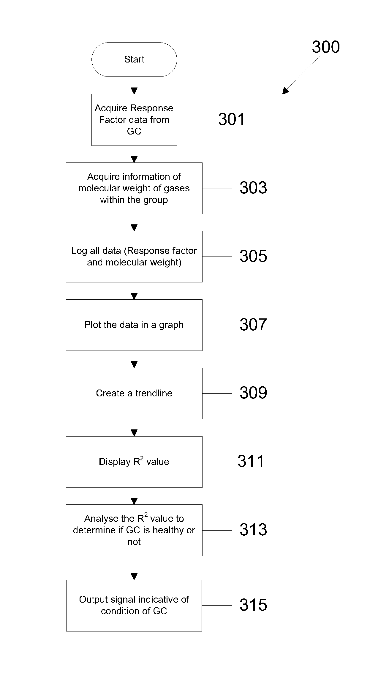
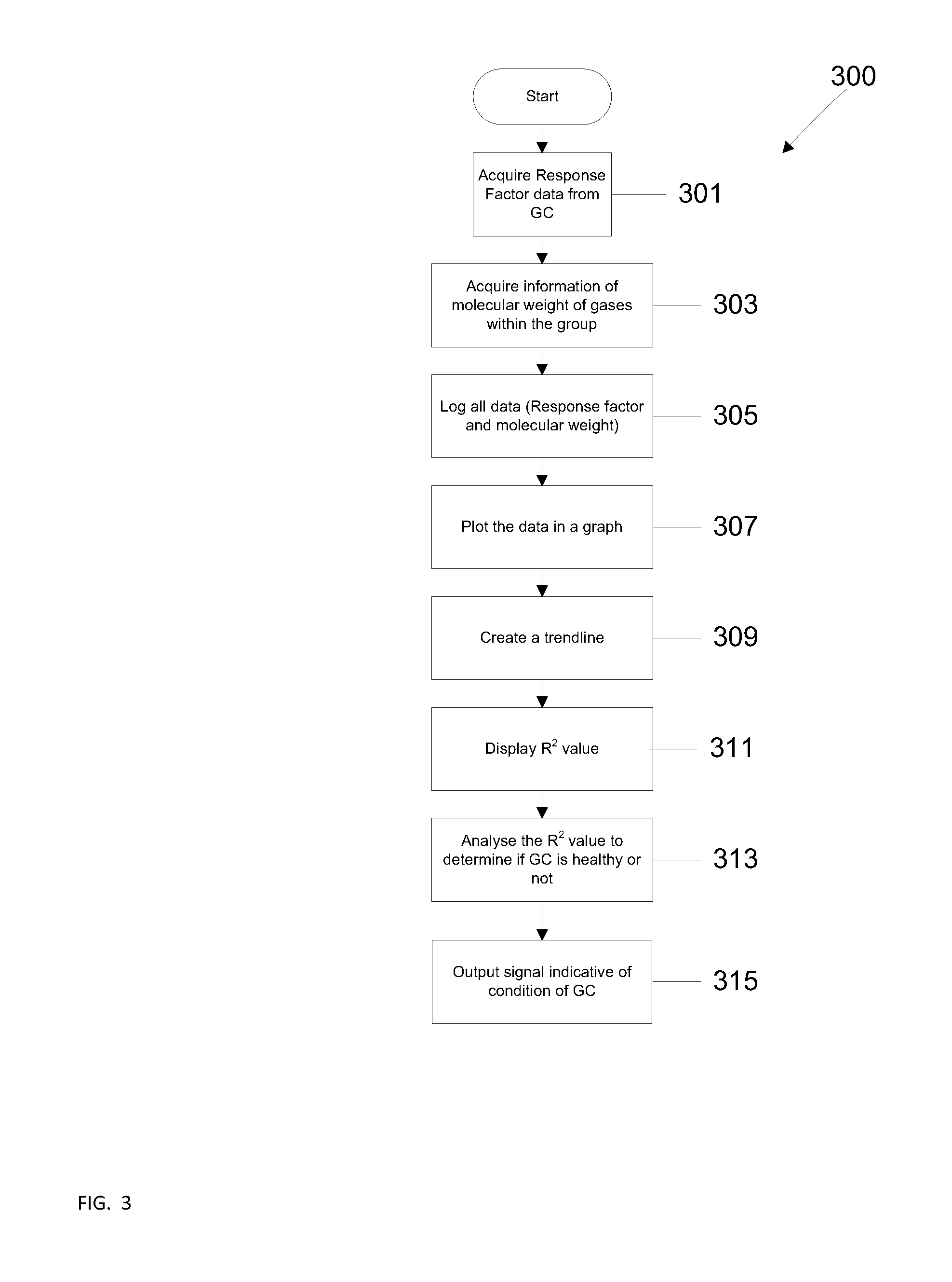
[0069]A first example is described with reference to FIGS. 10A and 10B, which are graphs 1000, 1001 of the Log(RF) data versus Log(MW) data for respective compound groups in a C7+ system. A comparison of the RF data for the C7 compound reveals the following: Log(RFC7)1C7 (i.e. the measured data is below the trend line); Log(RFC7)C7(footprint)) (i.e. the measured data is less than the corresponding footprint data); Log(RF) data for other compounds are similar to their respective footprint data (i.e. within a predetermined tolerance, such as 1%); and R2 for the C1-C2-C7 chart is less than a set threshold (normally set to 0.99).

[0070]This result can be explained by some of the heavy compounds leaving the first column 111, and flowing through column 112. This reduces the measured response factor of the heaviest component (C7+). The fault is due to a valve timing error on valve 102; it is actuating too late, and the fault can be addressed by decreasing the valve actuation time.

[0071]It w...

example 2

[0072]A second example is described with reference to FIGS. 11A and 118, which are graphs 1100, 1101 of the Log(RF) data versus Log(MW) data for respective compound groups in a C7+ system. A comparison of the RF data for the C6 and C7 compounds reveals the following:

Log(RFC6)1C6 (i.e. the measured data is below the trend line) Log(RFC6)C6(footpring)) (i.e. the measured data is less than the corresponding footprint data);

Log(RFC7)>y1C7 (i.e. the measured data is above the trend line); Log(RFC7)>Log(RFC7(footprint)) (i.e. the measured data is greater than the corresponding footprint data); Log(RF) data for other compounds are similar to their respective footprint data (i.e. within a predetermined tolerance, such as 1%); and R2 for the C1-C2-C7 chart and the C3-nC4-nC5-nC6 is less than a set threshold (normally set to 0.99).

[0073]This result may be explained by some of the middle components being back-flushed together with the heavy component. This increases the measured response facto...

example 3

[0074]A third example is described with reference to FIGS. 12A and 12B, which are graphs 1200, 1201 of the Log(RF) data versus Log(MW) data for respective compound groups in a C7+ system. A comparison of the RF data for the C2 compound reveals the following: Log(RFC2)1C2 (i.e. the measured data is below the trend line); Log(RFC2)C2(footpring)) (i.e. the measured data is less than the corresponding footprint data); Log(RF) data for other compounds are similar to their respective footprint data (i.e. within a predetermined tolerance, such as 1%); R2 for the C1-C2-C7 chart is less than a set threshold (normally set to 0.99); and R2 for the C3-C4-C5-C6 chart is greater than a set threshold (normally set to 0.99).

[0075]This result can be explained by some ethane being left in the second column 112, after the actuation of valve 113 to trap the light compounds. This reduces the measured response factor of the ethane (C2). The fault is due to a valve timing error on valve 103; it is actuati...


PUM


Abstract

A method of analyzing gas chromatography data may include acquiring response factor data for each of a plurality of compounds included in one or more calibration gas samples from a gas chromatograph apparatus, and determining a correlation with molecular weight data for each of the plurality of compounds. The correlation may be analyzed to determine a condition of the gas chromatograph. The method may also determine a correlation for each of a plurality of operating phases of the gas chromatograph, for example, before and after actuation of valves which change the flow rate. The method may also include diagnosing faults, and calibrating and configuring gas chromatographs.

Description

FIELD OF THE INVENTION[0001]The present invention relates to the field of gas chromatography, and, in particular, to a method of analyzing gas chromatography data, and methods of calibrating, monitoring, and / or maintaining gas chromatography equipment.BACKGROUND TO THE INVENTION[0002]Gas chromatography (GC) techniques are used in analytic chemistry applications to separate and / or analyze components of a mixture. Gas chromatography uses a carrier gas as its mobile phase, and a layer of liquid or polymer on a solid support as its stationary phase, located in a metal tube referred to as a column. Gaseous compounds in a sample being analyzed interact with the stationary phase as it passes through the column with the carrier gas. Different compounds interact at different rates and elute at different times. Analysis of the retention times of the compounds allows information to be derived about the compounds.[0003]Gas chromatography has numerous industrial applications. For example, it may...

Claims


Application Information

Patent Timeline
Patent Type & Authority Applications(United States)
IPC IPC(8): G06F19/00
CPCG01N2030/025G01N30/8665
Inventor SUTAN, ANWAR
Owner I VIGILANT
Why Eureka
Try Eureka