Air conditioning device for vehicle

a technology for air conditioning devices and vehicles, which is applied in refrigeration components, transportation and packaging, light and heating equipment, etc., can solve the problems of taking a long time for an occupant to feel comfortable warm, and achieve the effect of simple structure, rapid increase of the temperature of cooling water, and simple structur

Inactive Publication Date: 2012-01-26
CALSONIC KANSEI CORP
View PDF10 Cites 26 Cited by
  • Summary
  • Abstract
  • Description
  • Claims
  • Application Information

AI Technical Summary

Benefits of technology

[0030]The vehicle air conditioning device with a simple structure according to the present invention can rapidly increase the temperature of cooling water for heating the air in a vehicle cabin.
[0031]Moreover, the vehicle air conditioning device with a simple structure can rapidly increase the temperature of cooling water used for heating the air in a vehicle cabin in an engine start period in a low ambient temperature.

Problems solved by technology

In heating the air in a vehicle cabin with such a vehicle air conditioning device, it takes a long time for an occupant to feel comfortably warm because the air blown into the vehicle cabin is low in temperature until the temperature of the cooling water sufficiently rises.

Method used


Image

  • Air conditioning device for vehicle
  • Air conditioning device for vehicle
  • Air conditioning device for vehicle

Examples


first embodiment

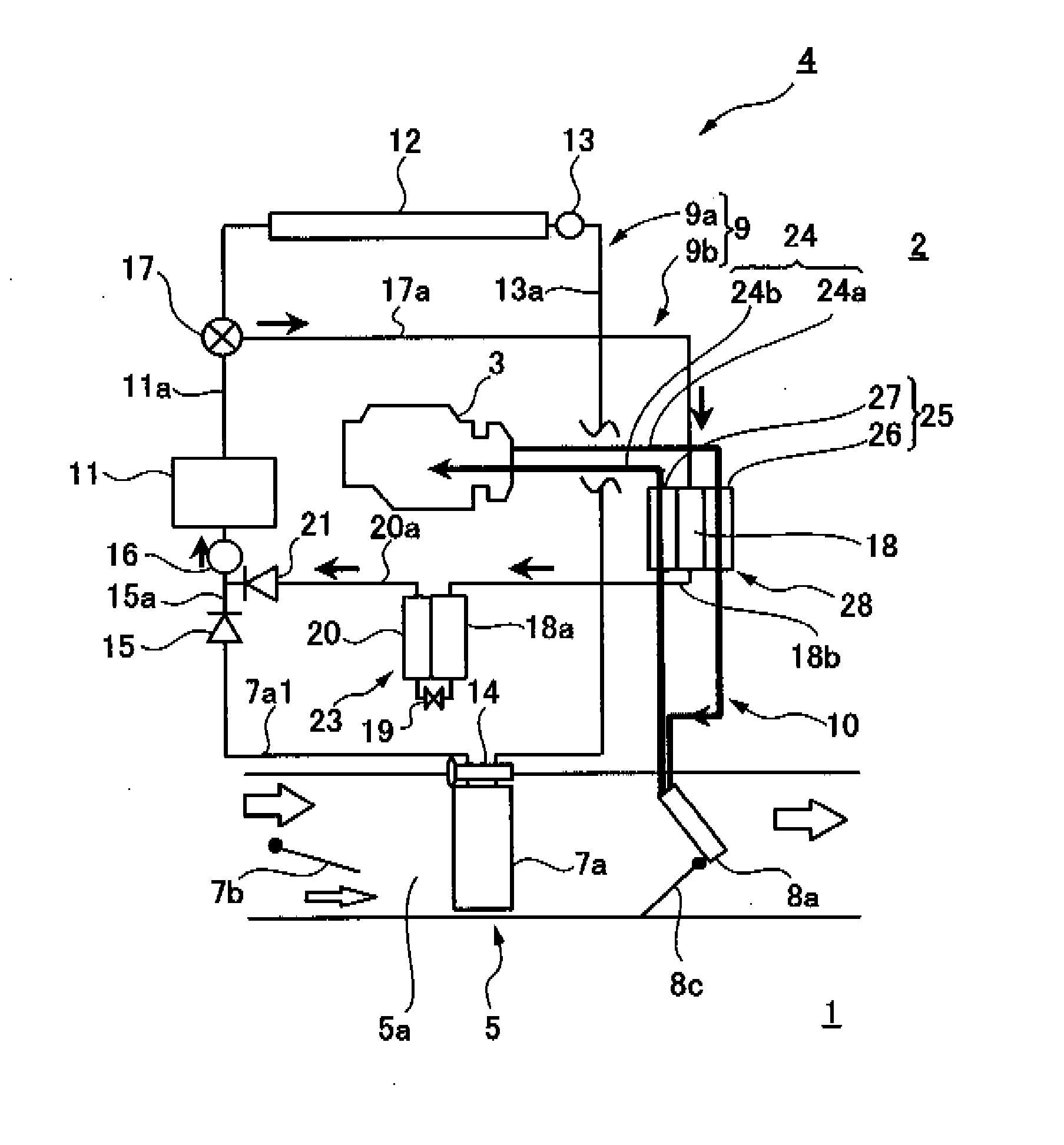
[0052]FIG. 1 schematically shows the structure of a vehicle air conditioning device according to a first embodiment of the present invention.

[0053]FIG. 1 shows a vehicle cabin 1 of a vehicle (automobile), a vehicle engine room 2, a water cooled engine 3 in the engine room 2. The engine 3 is provided with a known water jacket (not shown) for flowing engine cooling water for cooling the engine.

[0054]Further, an air conditioning unit 5 of a vehicle air conditioning device 4 is disposed in an instrument panel (not shown) at the front of the vehicle cabin 1.

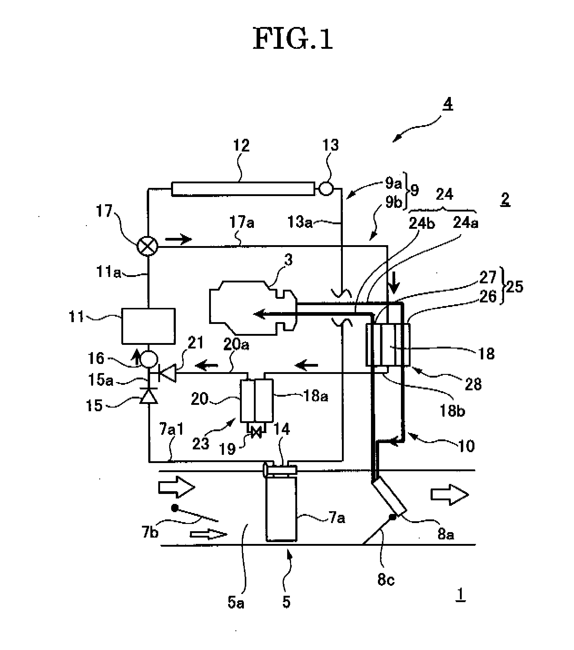
[0055]As shown in FIG. 2, the air conditioning unit 5 comprises a blower unit 6, a cooler unit 6, and a heater unit 8. An air passage 5a through which the air from the blower unit 6 flows is formed in the cooler unit 7 and the heater unit 8 of the air conditioning unit 5.

[0056]The blower unit 6 includes a blower (blowing fan) 6a and an intake unit 6b. The intake unit 6b has an outer air inlet 6b1, an inner air inlet 6b2, an intake doo...

first example of first embodiment

[0145]The above first embodiment has described an example where the first and second water heat exchangers 26, 27 to flow the engine cooling water supplied from to the water jacket of the engine 3 to the heater core 8a and to return the engine cooling water from the heater core 8a to the water jacket of the engine 3, respectively, are provided and the second external heat exchanger 18a for refrigerant condensation is disposed between the first and second water heat exchangers 26, 27. However, the present invention should not be limited to such an example.

[0146]For example, the second water heat exchanger 27 in FIG. 1 is omissible and instead, the first external heat exchanger 18 can be configured to heat the engine cooling water in the water heat exchanger 26a as shown in FIG. 6. In this case the water heat exchanger 26a and the first external heat exchanger 18 constitute the heat exchange means 28a for heating the cooling water.

second example of first embodiment

[0147]Further, the first water heat exchanger 26 in FIG. 1 is omissible and instead, the first external heat exchanger 18 can be configured to heat the engine cooling water in the water heat exchanger 27a as shown in FIG. 7. In this case the water heat exchanger 27a and the first external heat exchanger 18 constitute the heat exchange means 28b for heating the cooling water.


PUM


Abstract

Provided is a vehicle air conditioning device with a simple structure which can quickly raise the temperature of engine cooling water used for heating the air in a vehicle cabin in an engine start period in a low ambient temperature. The vehicle air conditioning device comprises the following elements integrally connected with each other: a first water heat exchanger (26) provided in the middle of a passage through which an engine cooling water flows from the water jacket of an engine (3) to a heater core (8a), a second water heat exchanger (27) provided in the middle of a passage through which the engine cooling water flows from the heater core (8a) to the water jacket of the engine (3), and a first external heat exchanger (18) for refrigerant condensation provided between the first and second water heat exchangers (26, 27). In the engine start period in a low ambient temperature, the engine cooling water flowing from the water jacket to the heater core (8a) is heated by heat released from the first external heat exchanger (18) to rise in temperature.

Description

TECHNICAL FIELD[0001]The present invention relates to a vehicle air conditioning device for air heating in a vehicle cabin using cooling water.BACKGROUND ART[0002]In general a vehicle air conditioning device includes an air heating unit using cooling water and an air cooling unit using a refrigeration cycle.[0003]A known air heating unit is configured to be able to heat the air in a vehicle cabin by circulating cooling water in a heater core for air conditioning of vehicle cabin (heat exchanger in vehicle cabin) and blowing the air having passed through the heater core from the air outlet of the vehicle cabin.[0004]In heating the air in a vehicle cabin with such a vehicle air conditioning device, it takes a long time for an occupant to feel comfortably warm because the air blown into the vehicle cabin is low in temperature until the temperature of the cooling water sufficiently rises.[0005]In order to resolve this, there is a known vehicle air conditioning device to heat the air in ...

Claims


Application Information

Patent Timeline
Patent Type & Authority Applications(United States)
IPC IPC(8): B60H1/03
CPCB60H1/03B60H2001/00949B60H1/00921B60H1/00914
Inventor NAKAJO, KAZUOTAKEI, TOSHIHIRONODA, YOSHITOSHIMARUYAMA, TOMOHIROHARA, JUNICHIRO
Owner CALSONIC KANSEI CORP
Why Eureka
Try Eureka