Low loss RF transceiver combiner

a low-loss, rf-based technology, applied in the direction of waveguide type devices, coupling devices, basic electric elements, etc., can solve the problems of limited the usefulness of n-way power dividers, difficult and expensive realization of n-way power splitters/combiners, etc., and achieve the effect of minimal loss of insertion loss

Inactive Publication Date: 2012-01-26
VISLINK TECH INC
View PDF6 Cites 20 Cited by
  • Summary
  • Abstract
  • Description
  • Claims
  • Application Information

AI Technical Summary

Benefits of technology

[0005]This disclosure describes a Radio Frequency (RF) splitter / combiner technique for splitting and combining the signals using a combination of microstrip traces and coaxial cable for an N-port network. The insertion loss experienced by this technique is minimal compared to traditional techniques used for splitting and combining RF signals.

Problems solved by technology

In applications where high volume, high power, low insertion loss, and low-cost component production is desirable, realizing an N-way power splitter / combiner is difficult and expensive, requiring the use of circuits assembled from multiple substrate layers and / or the use of discrete resistors rather than printed or etched resistors.
These costs and difficulties have limited the usefulness of N-way power dividers.

Method used


Image

  • Low loss RF transceiver combiner
  • Low loss RF transceiver combiner
  • Low loss RF transceiver combiner

Examples


Embodiment Construction

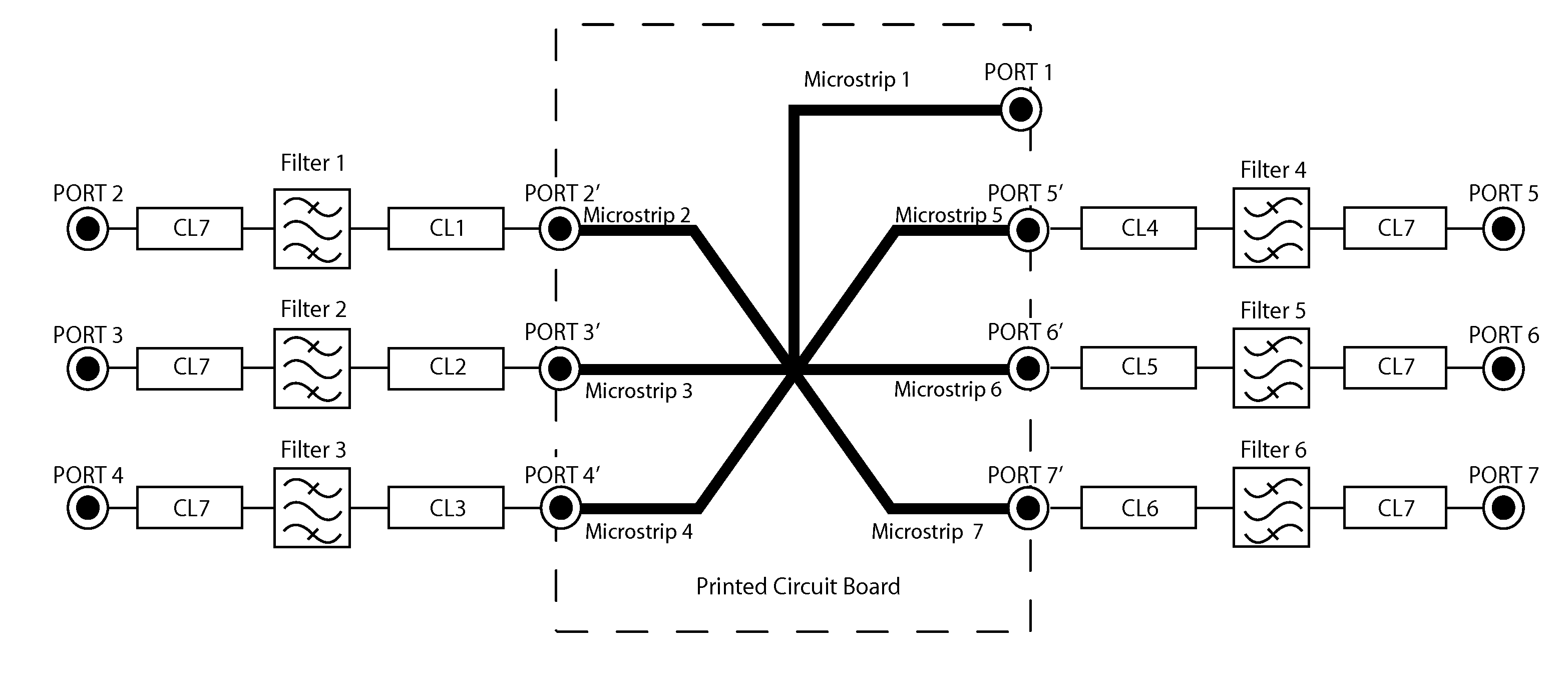
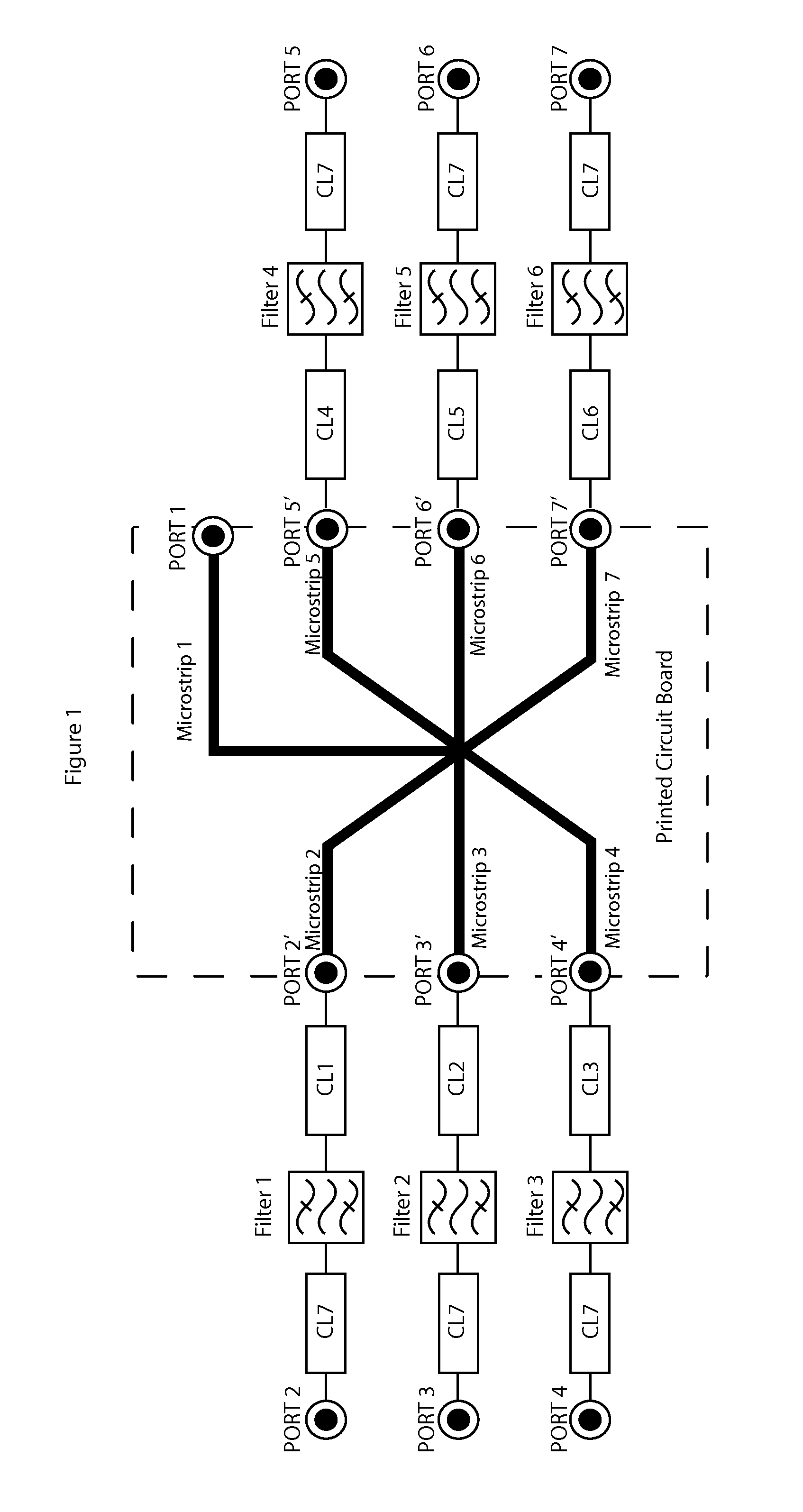
[0013]Splitter / combiners are electronic networks that provide one common port and two or more independent ports. When RF power is applied to the common port, and delivered to the independent ports, then the circuit operates as a splitter. When power is applied to the independent ports the combination of individual signals is added linearly at the common port, then the circuit operates as a combiner. The combiner is not a mixer because it is linear, and thus does not produce additional frequency products.

[0014]There are three main types of RF splitter / combiners: Zero Degree (0°), Ninety Degree (90°) hybrid and One Hundred Eighty Degree (180°) hybrid. Zero-degree RF dividers split an input signal into two or more output signals that are theoretically equal in both amplitude and phase. Zero-degree RF combiners join multiple input signals to provide one output. Ninety-degree hybrids split an input signal into two equal amplitude output signals, which are 90° out of phase from each other...


PUM


Abstract

A Radio Frequency (RF) splitter/combiner technique for splitting and combining RF signals using a combination of microstrip traces and coaxial cable for an N-port network is disclosed.

Description

CROSS-REFERENCE TO RELATED APPLICATION[0001]The present application claims the benefit of previously filed co-pending Provisional Patent Application Ser. No. 61 / 335,810 filed Jan. 12, 2010.FIELD OF THE INVENTION[0002]This invention addresses a method to split and combine RF signals. Specifically, this disclosure describes a Radio Frequency (RF) splitter / combiner technique for splitting and combining the signals using a combination of microstrip traces and coaxial cable for an N-port network. The insertion loss experienced by this technique is minimal compared to traditional techniques used for splitting and combining RF signals.BACKGROUND OF THE INVENTION[0003]Commonly used techniques for splitter / combiner realizations are Wilkinson (resistive, impedance matching transformer section of RF transmission line such as coaxial line, microstrip, stripline etc in various configurations), reactive and hybrid. In applications where high volume, high power, low insertion loss, and low-cost co...

Claims


Application Information

Patent Timeline
Patent Type & Authority Applications(United States)
IPC IPC(8): H01P1/20
CPCH01P5/12
Inventor KHAN, NADEEMPISTOLE, III, WILLIAM
Owner VISLINK TECH INC
Why Eureka
Try Eureka