Implantable MRI compatible medical lead with a rotatable control member

a technology of rotatable control and medical lead, which is applied in the field can solve the problems of increased rigidity, increased thickness increased rigidity of medical implantable lead, so as to reduce current induction, simple and cost-effective

Inactive Publication Date: 2012-01-26
ST JUDE MEDICAL
View PDF4 Cites 29 Cited by
  • Summary
  • Abstract
  • Description
  • Claims
  • Application Information

AI Technical Summary

Benefits of technology

[0008]It is an object of the invention to provide a medical implantable lead, which in a simple and cost-effective way reduces the induction of current from an electromagnetic field into the electrically conducting coil.

Problems solved by technology

This induced current may cause heating at an electrode being in contact with the tissue of the organ, especially if the electrode is in form of a helix which is penetrated into and embedded within the tissue.
If the heating is too high, there is a risk that this will cause damages to the tissue.
However, such shielded medical implantable leads are associated with several disadvantages.
On the one hand, the braided shielding will give the medical implantable lead an increased thickness as well as increased rigidity, which normally is not desirable.
On the other hand, it has appeared that such a braided shielding cannot prevent the induction of electrical current to the coiled conductor in a degree that is sufficient to, without risk, expose an individual, having an implanted lead, to a MRI-scanning.
Such a prior art medical implantable lead comprises passive electronic components, which contribute to making the lead more complex and thus more costly to manufacture.

Method used


Image

  • Implantable MRI compatible medical lead with a rotatable control member
  • Implantable MRI compatible medical lead with a rotatable control member
  • Implantable MRI compatible medical lead with a rotatable control member

Examples


first embodiment

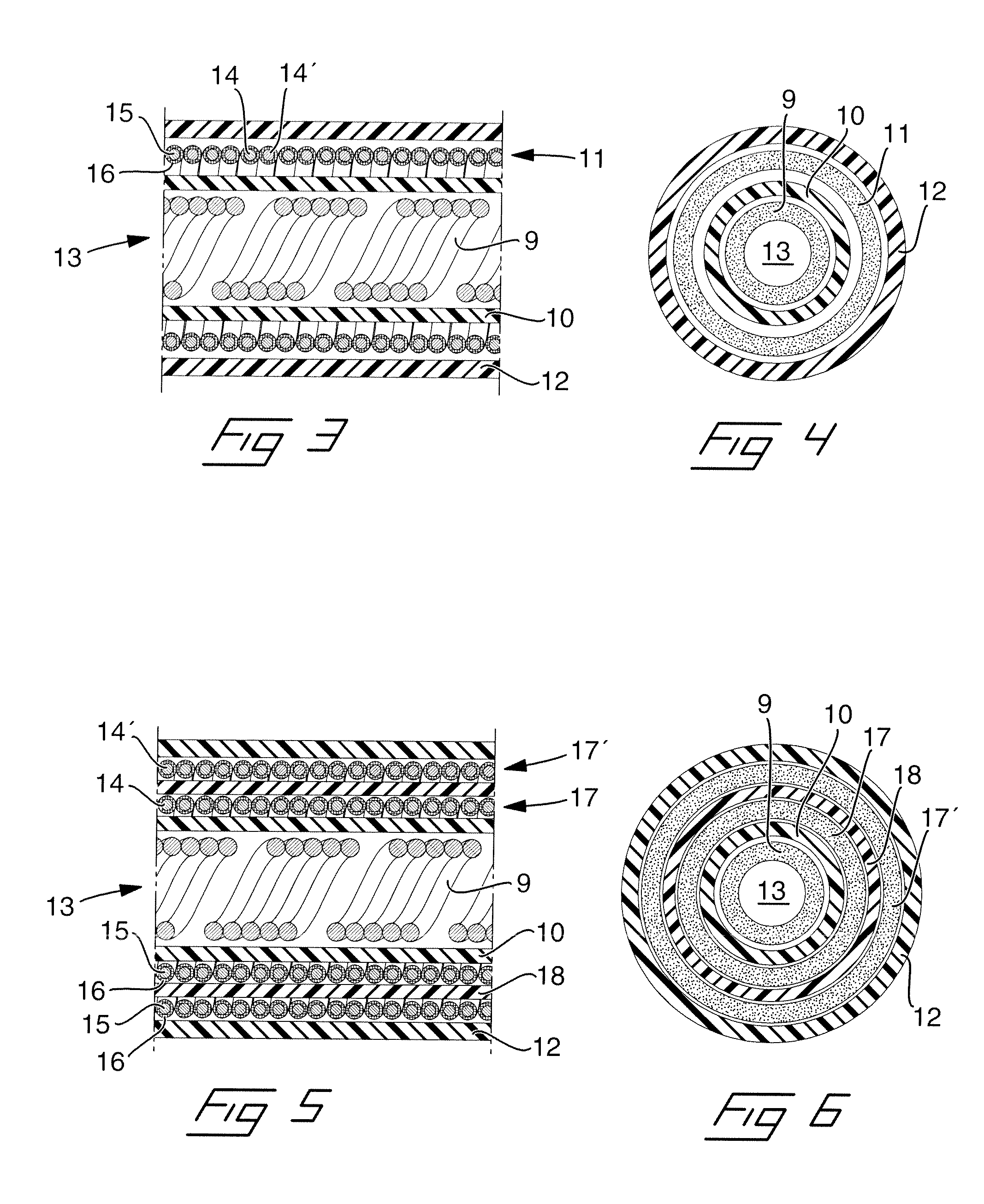
[0038]Now reference is made to FIGS. 3 and 4, in which are illustrated the flexible lead part 2 in a longitudinal section as well as a cross section through the lead, respectively. The lead comprises an inner tubular torque transferring member 9, an inner fluid tight tubing 10, an electrically conducting coil 11 and an outer fluid tight tubing 12. The inner tubular torque transferring member is rotatable arranged inside the inner tubing and is formed as a coil of five comparatively thick and rigid helical wires of e.g. metal or polymer, such that it is well suited for transferring of a torque from the proximal to the distal end of the lead. Moreover, the torque transferring member 9 defines an inner bore 13 for the purpose of allowing insertion of a guide wire or the like for guiding the tip of the lead to a desired position inside a body. The electrically conducting coil 11 is composed of two separate, co-radially wound wires 14, 14′, each having an electrically conducting core 15 ...

second embodiment

[0051]Reference is then made to FIGS. 13-15 in which is illustrated the arrangement of the connecting structure at the proximal end of the medical implantable lead according to the invention.

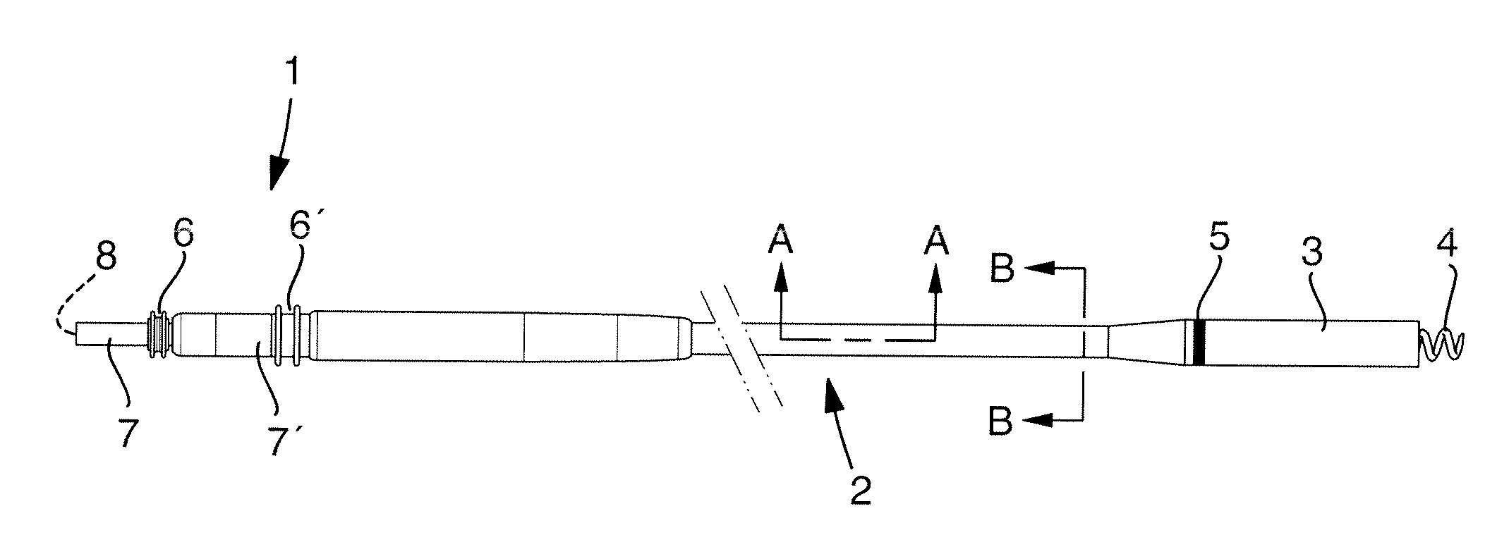
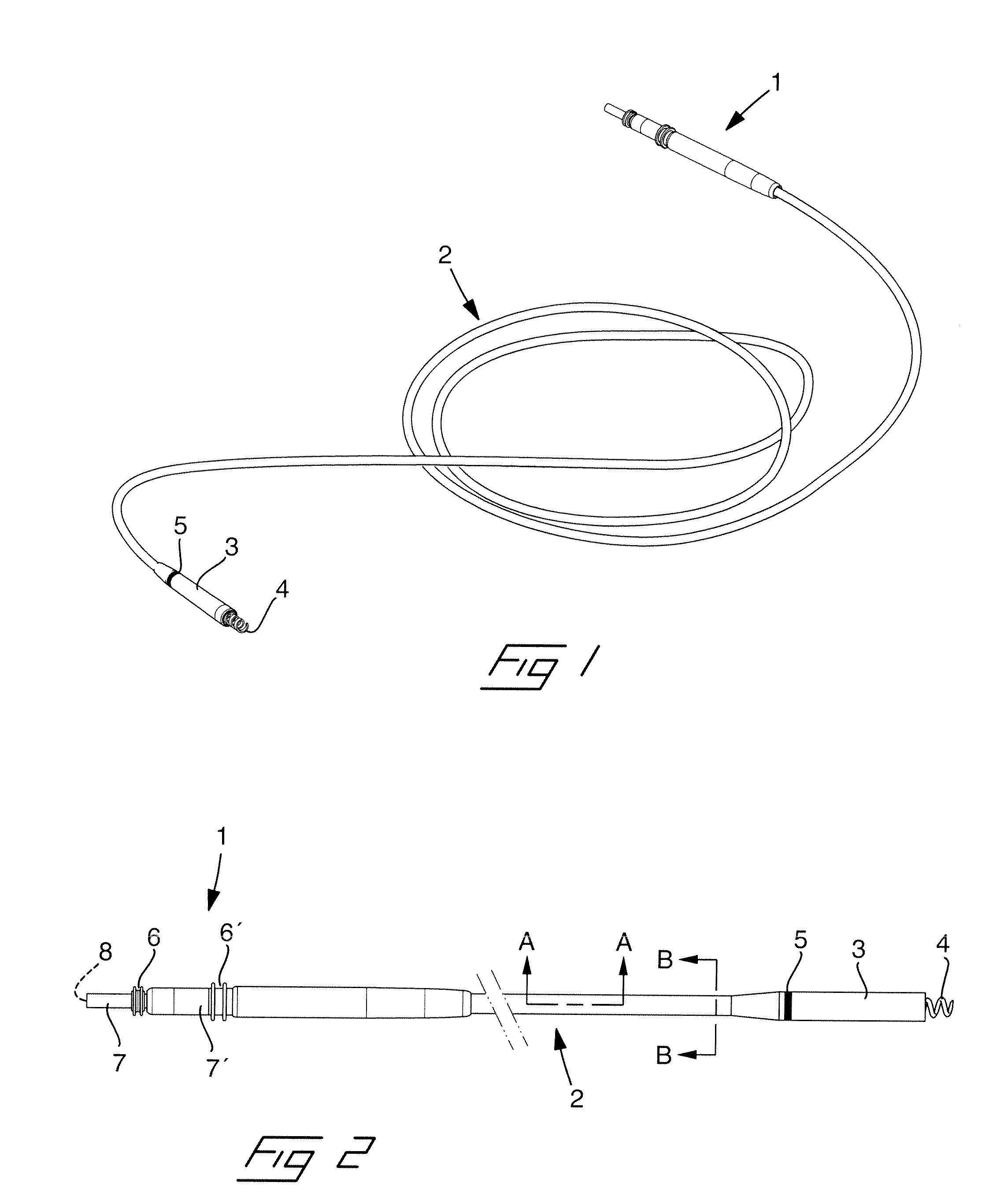
[0052]As in the embodiment according to FIGS. 9-11, the connecting structure according to this embodiment comprises a thickened portion 25 and a connector pin 26 protruding from the proximal end of the thickened portion. A first fluid tight sealing member 6 is arranged around the connector pin adjacent the proximal end of the thickened portion. A second fluid tight sealing member 6′ is arranged around the thickened portion in an intermediate position of the same.

[0053]Moreover, the connector pin 26 is composed of an inner rotatable control member 8, which is connected to the inner torque transferring member 9 and is rotatably arranged within an outer, tubular electrically conducting connector 7, which in its turn is unrotatably mounted to the thickened portion and electrically connected to the h...


PUM


Abstract

A medical implantable lead is adapted to be implanted into a human or animal body for monitoring and/or controlling of an organ inside the body. The lead has in a distal end, a combined fixation means and electrode member in form of a helix, which is connected to a rotatable tubular member being connected to a rotatable member at a proximal end of the lead, and which is rotatable in relation to the lead and extendable out from the distal end, by rotation of the control member and the tubular torque transferring member, to be able to fixate the distal end of the lead to the organ by being screwed into the tissue. The helix is electrically connected to a connector at the proximal end by means of at least one electrically conducting wire formed as an electrically conducting coil, which is separate from the tubular torque transferring member and unrotatable in relation to the lead and that has one or more individual wires, each including an electrically conducting wire core and a surrounding electrically insulating layer, wherein the rotatable control member is rotatable within the connector.

Description

BACKGROUND OF THE INVENTION[0001]1. Field of the Invention[0002]The invention relates to a medical implantable lead of the kind being adapted to be implanted into a human or animal body for monitoring and / or controlling of an organ inside the body, comprising at a distal end a combined fixation means and electrode member in form of a helix, which is connected to a rotatable tubular torque transferring member being in its turn connected to a rotatable control member at a proximal end of the lead, and which is rotatable in relation to the lead and extendable out from the distal end, by rotation of the control member and the tubular torque transferring member, to be able to fixate the distal end of the lead to the organ by being screwed into the tissue, wherein the helix is electrically connected to a connector at the proximal end by means of at least one electrically conducting wire.[0003]2. Description of the Prior Art[0004]It is well known in the art to use a medical implantable lea...

Claims


Application Information

Patent Timeline
Patent Type & Authority Applications(United States)
IPC IPC(8): A61N1/05A61B5/04
CPCA61N1/3752A61N1/057
Inventor OLSEN, LINNFORSLUND, MIKAELDJURLING, HENRIKFORSSTROM, PATRIKHENRIQUEZ, LEDADAHLBERG, KENNETHSTEGFELDT, OLOFSIVARD, KE
Owner ST JUDE MEDICAL
Why Eureka
Try Eureka