Composite orthopedic implant having a low friction material substrate with primary frictional features and secondary frictional features

a composite orthopedic and substrate technology, applied in the field of composite orthopedic implants having a low friction material substrate, can solve the problems of post-operative expulsion or dislocation of the implanted device, undesirably low frictional force between bone and the implanted device, and the inherent low level of bone-device surface interaction of the polymer spinal implant, etc., to achieve low lubricity, low elasticity, and simple frictional features

Inactive Publication Date: 2012-01-26
X SPINE SYST
View PDF5 Cites 43 Cited by
  • Summary
  • Abstract
  • Description
  • Claims
  • Application Information

AI Technical Summary

Benefits of technology

[0008]One object of an embodiment is to provide simple frictional features that add a metallic surface material which has features of low lubricity, low elasticity and secondary frictional features. Such a design will maintain the desirable biomechanical properties of the polymeric implant itself while addressing frictional shortcomings at the bone-device interface. Physical properties of the metallic surface can be further optimized using dispersed deposition techniques onto the polymeric substrate.
[0012]Still another object is to provide a surgical implant having improved frictional engagement at the bone-implant engaging interfaces.
[0017]In one aspect, one embodiment comprises an orthopedic implant comprising a substrate material adapted to provide the orthopedic implant, a primary friction area located on or integral with the substrate material, the primary friction area having a primary surface having a primary frictional feature and a secondary friction area located on or integral with the primary surface and defining a secondary frictional feature, the primary friction area and the secondary friction area defining a friction interface zone, the secondary friction area increasing a friction of the primary surface to enhance the frictional engagement between the primary surface and at least one bone.
[0018]In another aspect, another embodiment comprises an orthopedic implant comprising a body comprising a composite material, a first friction area situated between the body and bone of a patient when the orthopedic implant is implanted in the patient and a second friction area associated with the first friction area for directly engaging the bone, each of the first and second friction areas for improving a frictional engagement between the bone and the orthopedic implant.

Problems solved by technology

One risk of such procedures is the post-operative expulsion or dislocation of the implanted device.
A significant problem, however, with the use of such polymeric spinal implants is inherent low levels of bone-device surface interaction.
This can result in undesirably low frictional forces between bone and the implanted device.
Although surface teeth increase interface friction somewhat, the underlying challenges of lubricity, smoothness and elasticity remain.

Method used


Image

  • Composite orthopedic implant having a low friction material substrate with primary frictional features and secondary frictional features
  • Composite orthopedic implant having a low friction material substrate with primary frictional features and secondary frictional features
  • Composite orthopedic implant having a low friction material substrate with primary frictional features and secondary frictional features

Examples


Embodiment Construction

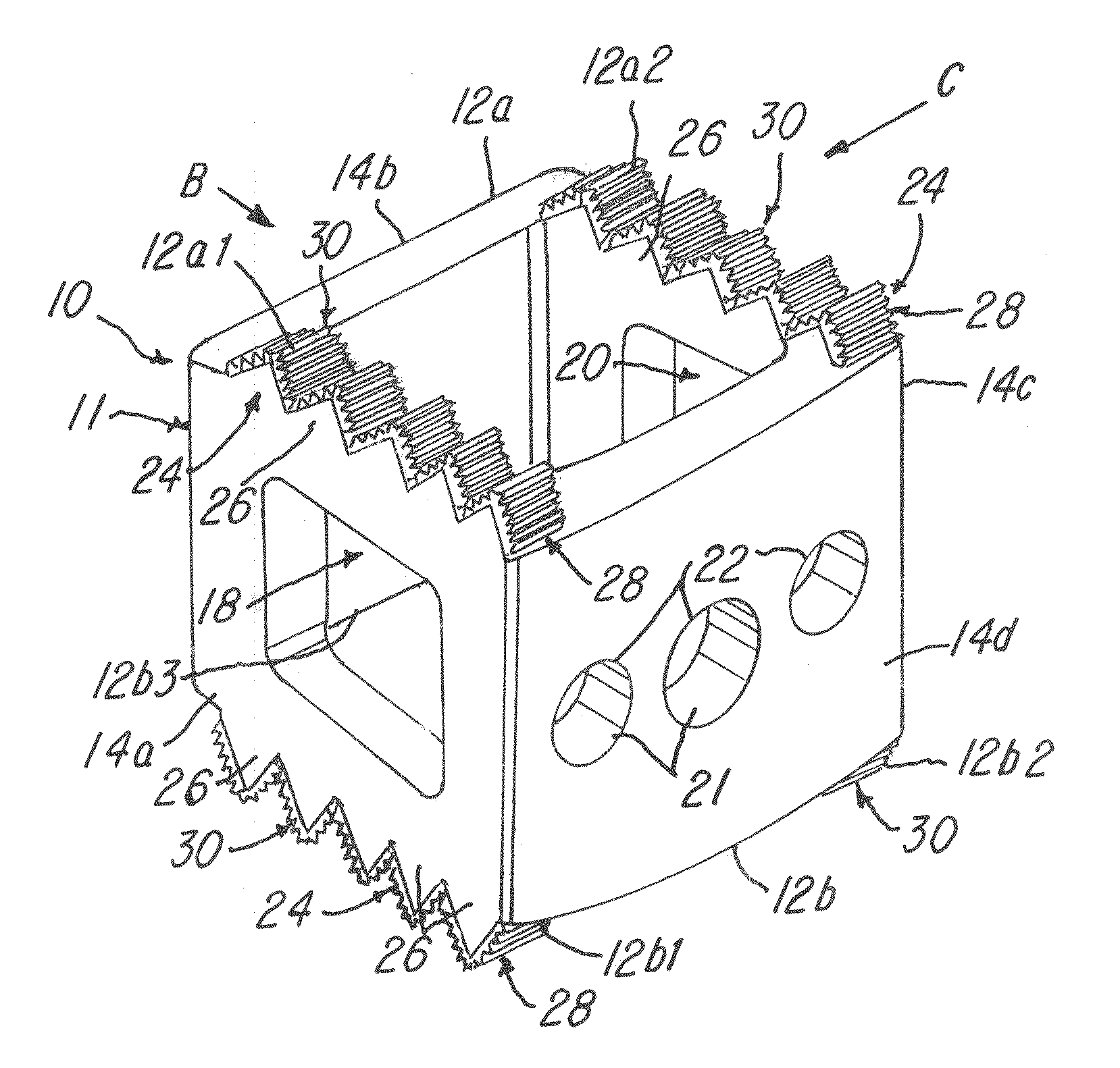
[0034]Referring now to FIGS. 1-5, a first embodiment of an orthopedic implant 10 is shown. The orthopedic implant 10 comprises a body 12 that is adapted to provide or define the orthopedic implant 10. In the illustration being described, the orthopedic implant 10 could be a spinal implant, such as a cage, plate or other implant wherein surfaces of the orthopedic implant 10 engage, for example, bone of a patient. In one application, the orthopedic implant 10 is situated between adjacent vertebrae (not shown) of a patient. In the illustration being described, the orthopedic implant 10 comprises the body 12 made from a substrate or composite material, such as a polymeric material. The polymeric material may be a thermoplastic material, such as polyetheretherketone (PEEK). The substrate or composite material has a low coefficient of friction with bone.

[0035]The orthopedic implant 10 defines an orthopedic cage 11 in this illustration having a plurality of walls 14a, 14b, 14c and 14d. The...


PUM

PropertyMeasurementUnit
frictionaaaaaaaaaa
secondary frictionaaaaaaaaaa
thermoplasticaaaaaaaaaa

Abstract

An orthopedic implant comprising a substrate material adapted to provide the orthopedic implant. The implant has a primary friction area located on or integral with the substrate material. The primary friction area defining an engagement surface having a primary frictional feature. A secondary friction area is located on or integral with the engagement surface and defining a second frictional feature. The primary friction area and the secondary friction area defining a friction interface zone between the orthopedic implant and at least one bone. The secondary friction area increases a friction of the engagement surface and modulus of elasticity to enhance the frictional engagement between the engagement surface and the at least one bone.

Description

CROSS-REFERENCE TO RELATED APPLICATION[0001]The present application claims priority to provisional U.S. Application Ser. No. 61 / 365,912 filed Jul. 20, 2010, to which Applicant claims the benefit of the earlier filing date. This provisional application is incorporated herein by reference and made a part hereof.BACKGROUND OF THE INVENTION[0002]1. Field of the Invention[0003]This invention relates to a composite orthopedic implant having a low friction material substrate with primary frictional features and secondary frictional features.[0004]2. Description of the Related Art[0005]The placement of spinal implants between vertebrae is a common surgical procedure. A number of such spinal implants, which are generally hollow and box-shaped or cylindrical, have been developed. One risk of such procedures is the post-operative expulsion or dislocation of the implanted device. There is a need to increase the frictional forces between the device and the bone surface.[0006]The most advantageou...

Claims


Application Information

Patent Timeline
Patent Type & Authority Applications(United States)
IPC IPC(8): A61F2/44
CPCA61F2/30767A61F2310/00413A61F2/4611A61F2002/30014A61F2002/30024A61F2002/30321A61F2002/30448A61F2002/30451A61F2002/30769A61F2002/30789A61F2002/30841A61F2002/30892A61F2002/30904A61F2002/30906A61F2002/3092A61F2002/30924A61F2002/30929A61F2002/3098A61F2250/0021A61F2310/00407A61F2/447A61F2/3094A61F2002/30922A61F2/30771A61F2002/30838A61F2002/30968
Inventor KIRSCHMAN, DAVID LOUIS
Owner X SPINE SYST
Why Eureka
Try Eureka