A fluid control valve

a fluid control valve and valve body technology, applied in valve housings, machines/engines, lighting and heating apparatus, etc., can solve the problems of reduced lubrication performance, increased wear, fuel consumption, etc., and achieve the effect of easy actuation, low cost and small dimension

Active Publication Date: 2017-02-23
VOLVO LASTVAGNAR AB
View PDF25 Cites 12 Cited by
  • Summary
  • Abstract
  • Description
  • Claims
  • Application Information

AI Technical Summary

Benefits of technology

[0054]The term pilot valve refers to a valve that indirectly controls the axial position of the main valve. The pilot valve has a smaller dimension that the main valve and is therefore more easily actuated that the main valve.
[0055]The term electro-mechanical actuator refers to all types of actuators that can mechanically control the position of the pilot valve using electrical energy. A linear electro-mechanical actuator cooperating with an axially displaceable pilot valve is a preferred design due to its relatively non-complexity and low-cost. The invention is however not limited to this design and many alternative designs are possible, such as angular actuators, turning actuators, etc. Furthermore, the actuator as such may be based on solenoid technology, screw thread, or any other technology for generating a mechanical actuation by electrical power.

Problems solved by technology

One parameter affecting fuel consumption is the internal resistance within the engine and transmission, and this internal resistance is a function of the viscosity of the lubrication oil within the combustion engine.
Low viscosity oil means less resistance but too low viscosity results in reduced lubrication performance, increased wear, reduced lifetime and potential engine damages.
This conventional technology for controlling the oil temperature is however not particularly reliable and reacts slowly to changes in incoming oil temperature, Consequently, engine provider are forced to set the oil operating temperature relatively low for the purpose of providing a sufficiently large temperature safety range up to the maximal allowed oil temperature, thereby automatically also operating the engine with an unnecessary high level of internal friction.
The electro-mechanical actuator can generally generate a relatively low actuating force, thereby making the actual position of a piston of the actuator uncertain when operating directly on the main valve, due to the relatively high forces acting on the main valve, such as the fluid pressure, main valve spring member and main valve sliding friction.

Method used


Image

  • A fluid control valve
  • A fluid control valve
  • A fluid control valve

Examples


Embodiment Construction

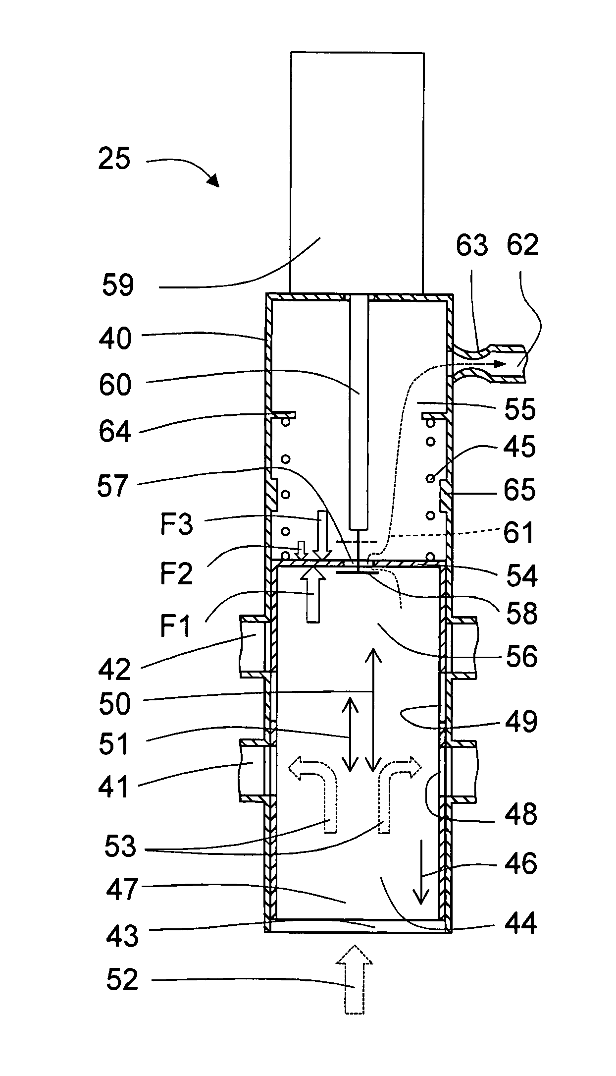
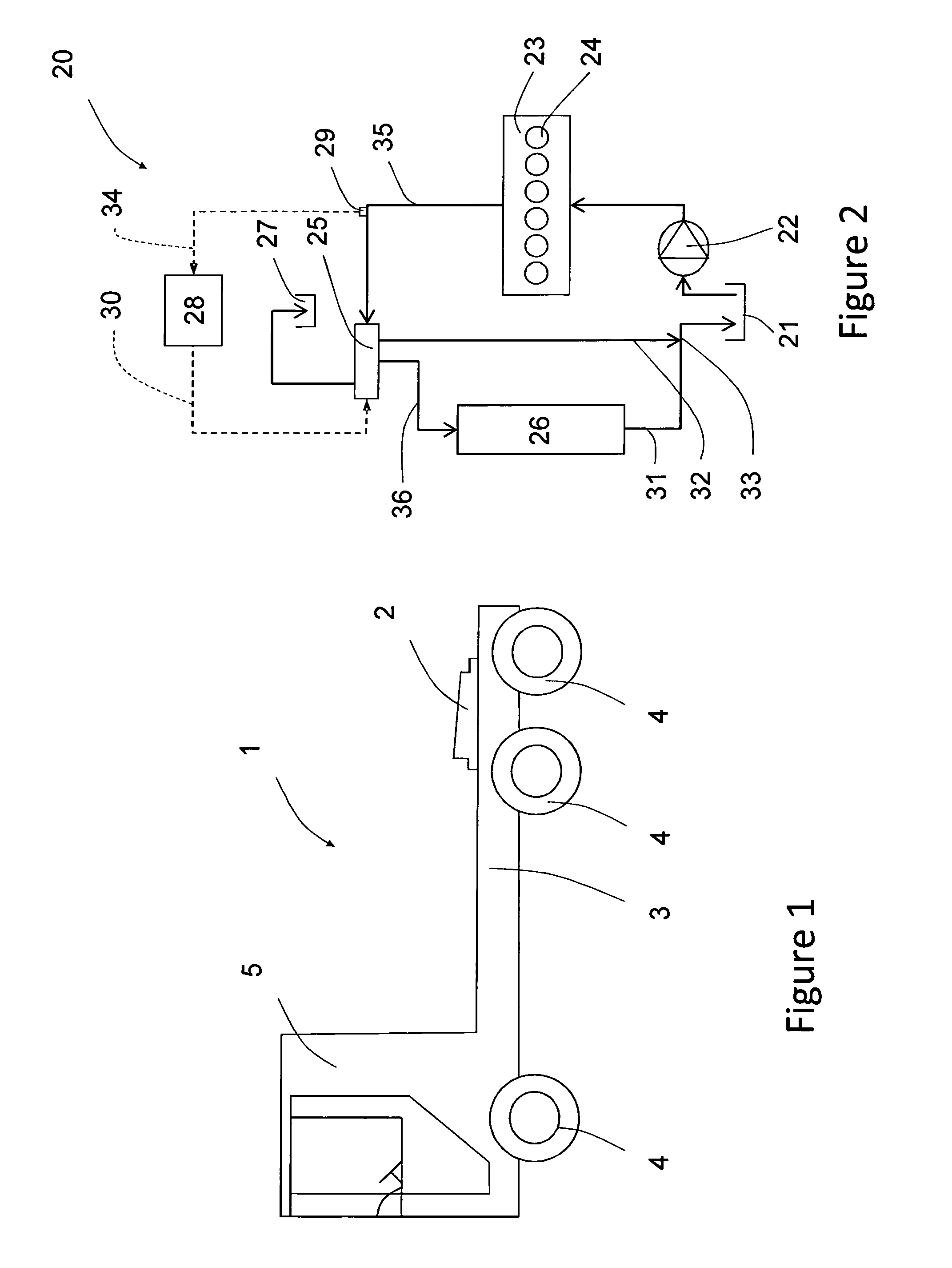
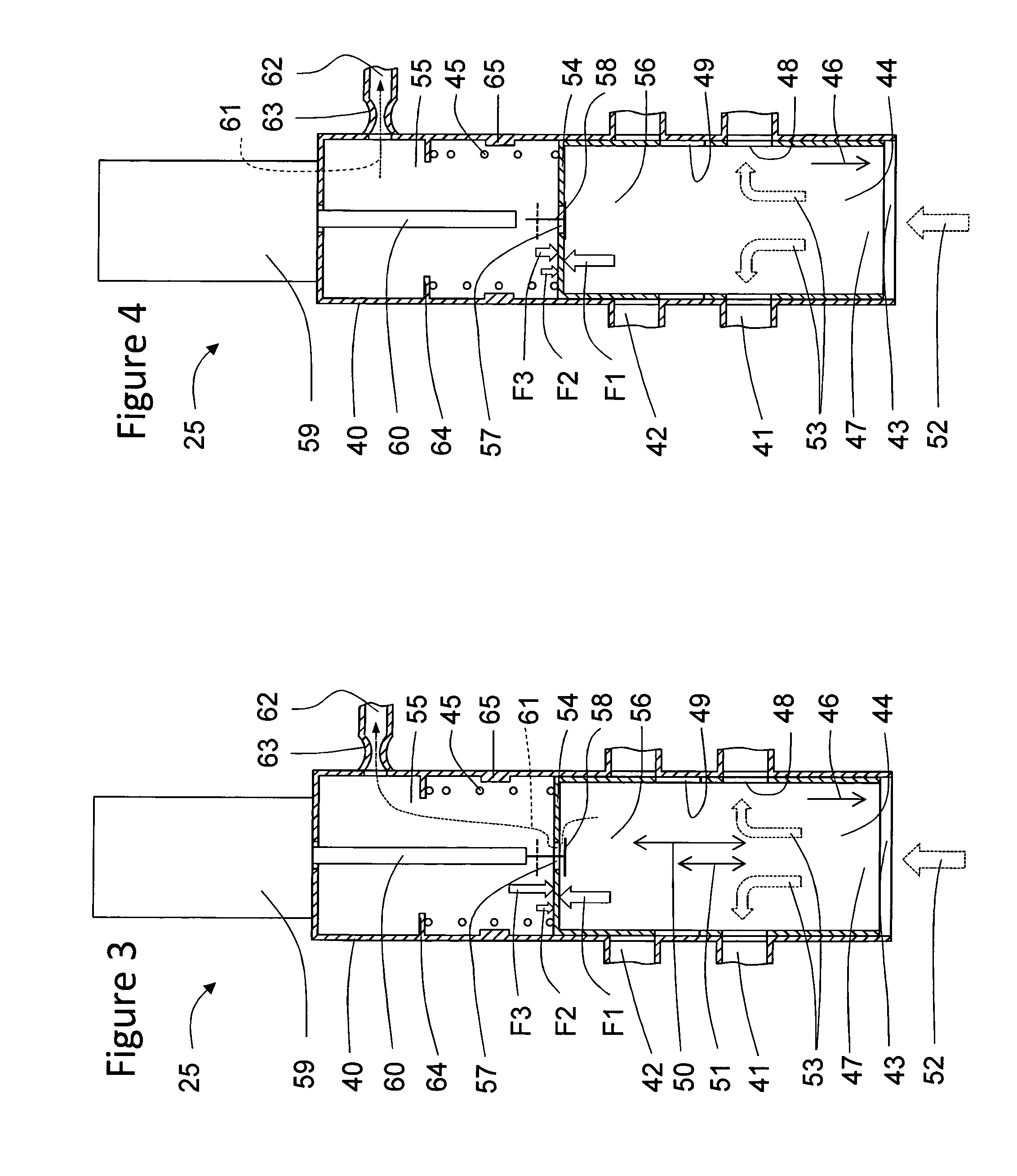
[0070]Embodiments of the fluid control valve, heat exchange system and method for adjusting the axial position of the main valve of the fluid control valve will now be described with reference to the accompanying figures, wherein like numerals refer to like or similar elements throughout. Although several embodiments, examples and illustrations are disclosed below, it will be understood by those of ordinary skill in the art that the inventions described herein extends beyond the specifically disclosed embodiments, examples and illustrations, and can include other uses of the inventions and obvious modifications and equivalents thereof. The terminology used in the description presented herein is not intended to be interpreted in any limited or restrictive manner simply because it is being used in conjunction with a detailed description of certain specific embodiments of the inventions. In addition, embodiments of the inventions can comprise several novel features and no single featur...


PUM


Abstract

A fluid control valve includes a cylindrical housing with at least one opening through a housing wall, a cylindrical main valve axially movably arranged inside the housing for controlling a fluid flow through the at least one opening and a main valve spring member acting on the main valve. The main valve includes a base wall defining a fluid control volume and fluid main volume in the cylindrical housing. The base wall includes an opening for fluidly connecting the fluid control volume with the fluid main volume. The fluid control valve further includes a pilot valve positioned at the base wall opening, which pilot valve is moveably arranged for controlling a fluid flow through the base wall opening, and an electro-mechanical actuator configured to act on the pilot valve for controlling the main valve via the pilot valve. A method for adjusting the axial position of a cylindrical main valve of a fluid control valve is also provided.

Description

BACKGROUND AND SUMMARY[0001]The invention relates to a fluid control valve comprising a cylindrical housing with at least one opening through a housing wall, a cylindrical main valve axially movably arranged inside the housing for controlling a fluid flow through the at least one opening and a main valve spring member acting on the main valve. The invention also relates to a heat exchange system comprising a heat exchange fluid circuit having a heat source, a heat exchanger, a heat exchanger by-pass, a fluid pump and a fluid control valve, as well as a method for adjusting the axial position of a cylindrical main valve of a fluid control valve.[0002]The fluid control valve according to the invention is particularly suitable as flow control valve in heat exchange systems having a heat exchanger device and a bypass line, where the fluid control valve according to the invention is arranged to control the ratio of flow through the heat exchanger device and bypass line. The heat exchange...

Claims


Application Information

Patent Timeline
Patent Type & Authority Applications(United States)
IPC IPC(8): F01M5/00F16K11/07F01P7/14F16K27/04F16K1/12F28F27/02F16K31/122F16K31/42
CPCF01M5/005F16K31/1221F16K11/07F16K31/426F01P2007/146F16K1/126F28F27/02F01P7/14F16K27/041F01P7/165F16K3/24F16K3/26F16K3/267F16K27/048F16K3/262F16K31/12F16K31/42
Inventor LAGERLOF, FREDRIK
Owner VOLVO LASTVAGNAR AB
Why Eureka
Try Eureka