

Control System in a Vehicle
a control system and vehicle technology, applied in electric/magnetic computing, analogue processes for specific applications, instruments, etc., can solve problems such as making the driver's driving feeling worse, and achieve the effect of increasing the cost and improving the driving feeling
- Summary
- Abstract
- Description
- Claims
- Application Information
AI Technical Summary
Benefits of technology
Problems solved by technology
Method used
Image

Examples
embodiment 1
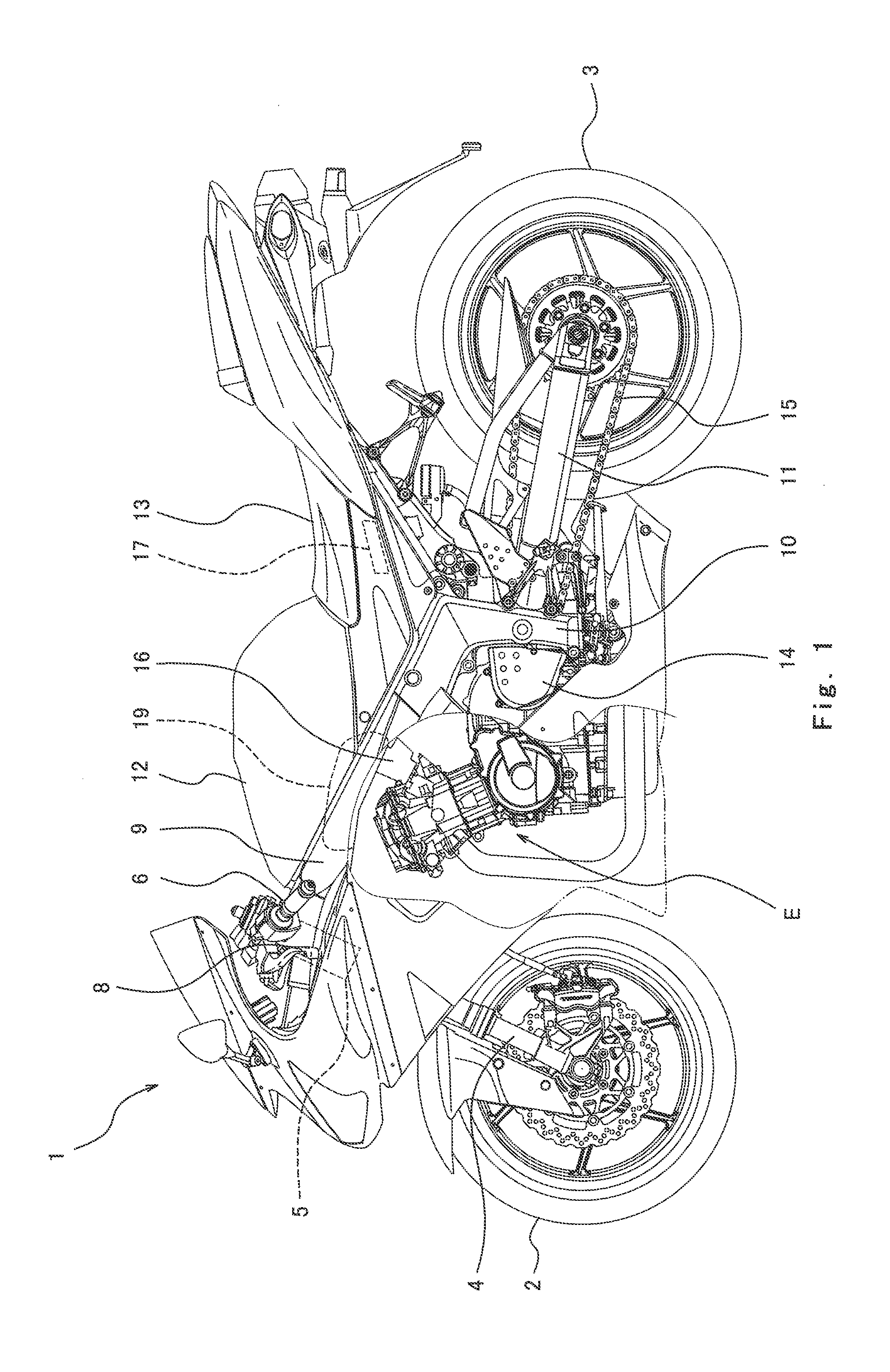
[0042]FIG. 1 is a left side view of a motorcycle 1 (vehicle) according to Embodiment 1 of the present invention. Referring to FIG. 1, the motorcycle 1 includes a front wheel 2 which is a driven wheel and a rear wheel 3 which is a drive wheel. The front wheel 2 is rotatably mounted to the lower end portion of a front fork 4 extending substantially vertically. The front fork 4 is attached to a steering shaft (not shown) via brackets (not shown). The steering shaft is rotatably supported by a head pipe 5 provided at a vehicle body.
[0043]A bar-type steering handle 6 extending in a rightward and leftward direction is attached to the brackets. By maneuvering the steering handle 6, the driver steers the front fork 4 and the front wheel 2. A throttle grip 7 (see FIG. 4) is provided at a right end portion of the steering handle 6 which is gripped by the driver's right hand. The throttle grip 7 is rotated by twisting the driver's wrist to operate a throttle device 16 as described later. A clu...
modified example
[0103]In modified example of Embodiment 1, both of the two determiners 61 and 62 need not be used, but instead, only the first determiner 61 for performing determination as to the non-contact state based on only the change rate of the input shaft rotational speed Vi may be used. In this case, for example, as shown in the flowchart of FIG. 10, it is determined whether or not the difference ΔVi of the input shaft rotational speed Vi is greater than a differential threshold ΔVi1+ which is a positive value (step T1). If Yes (ΔVi>ΔVi1+) in step T1, calculation for ignition skip or ignition retard is performed to reduce the rotational speed Vi of the input shaft 24 (step T2). Then, it is determined whether or not a condition used for inhibiting the execution of the acceleration or deceleration control is not met (step T3). If the condition is not met in step T3, then the acceleration or deceleration control (in this case deceleration control) is performed (step T4).
[0104]If the answer is ...
embodiment 2
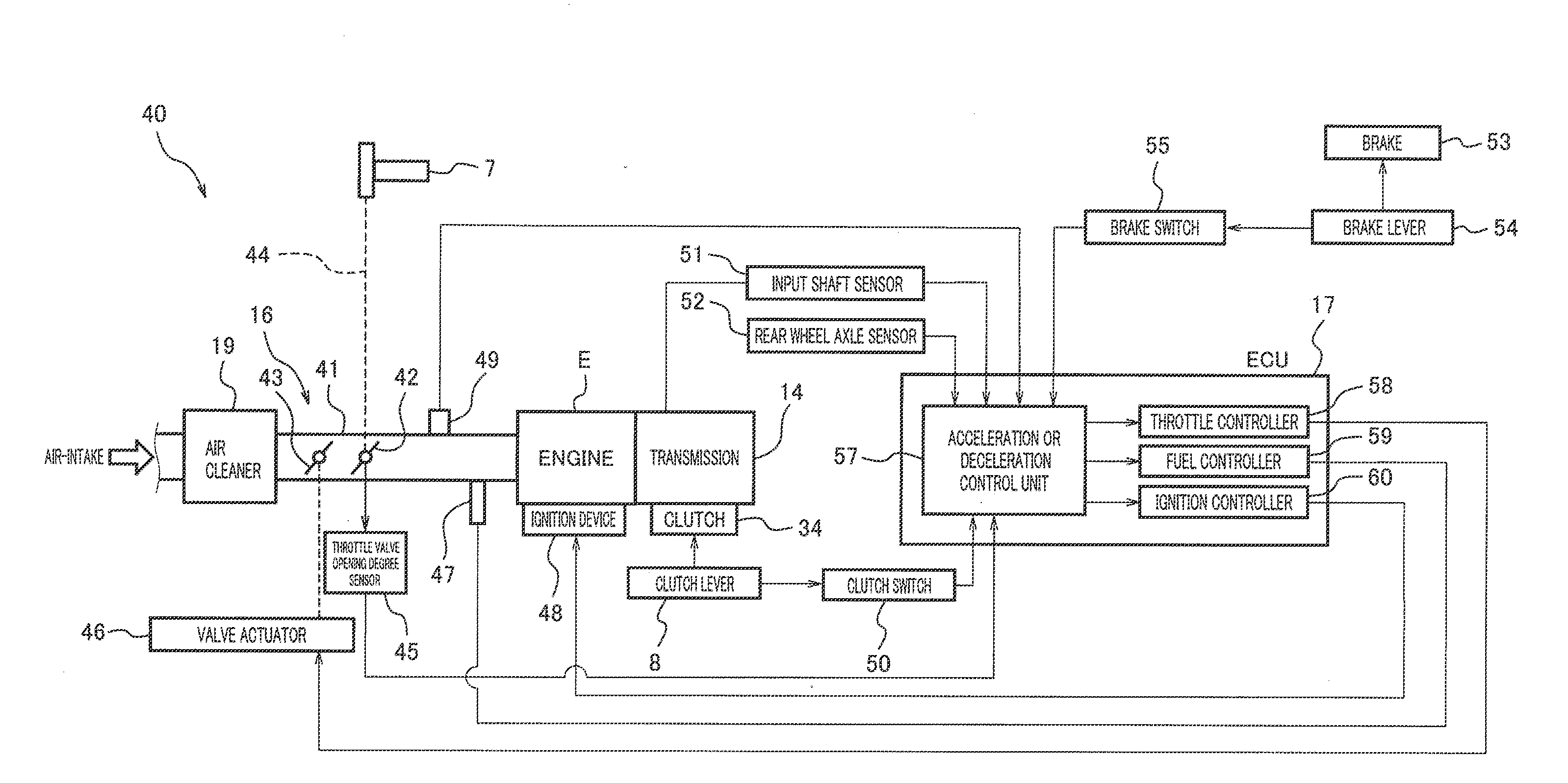
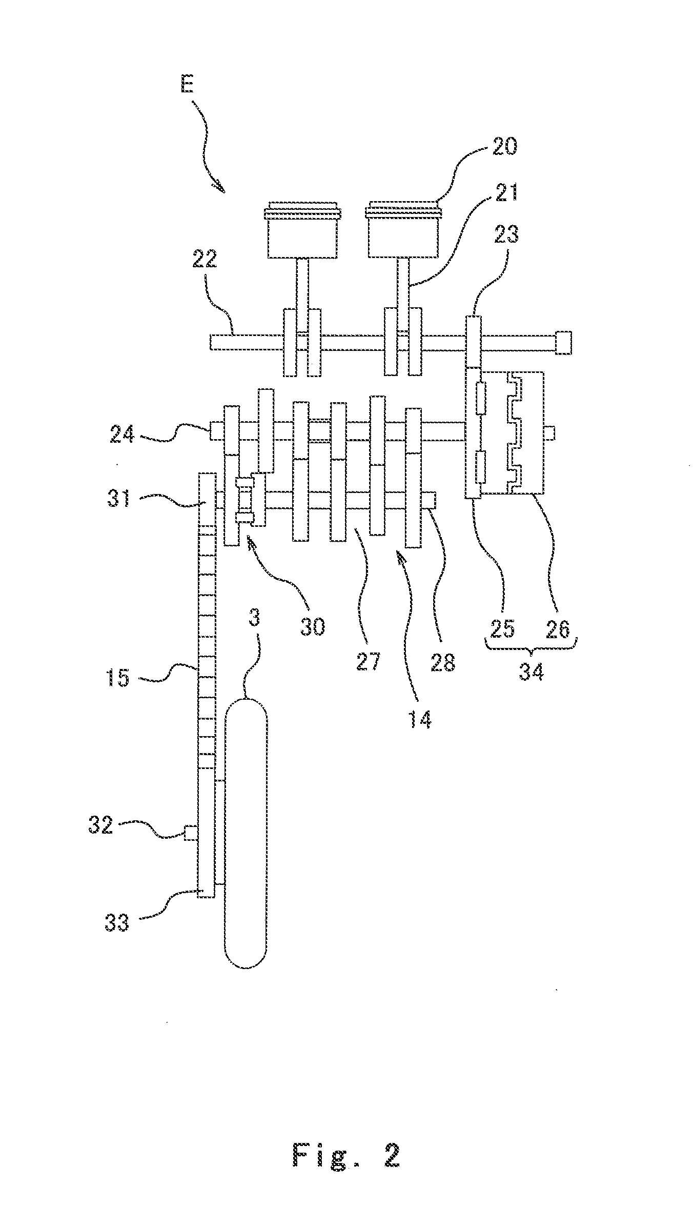
[0106]FIG. 11 is a block diagram showing major components in a vehicle control system 140 according to Embodiment 2 of the present invention. The same components as those in Embodiment 1 are identified by the same reference symbols and will not be described repetitively. Referring to FIG. 11, the vehicle control system 140 of Embodiment 2 includes an output shaft assist motor 73 for driving the output shaft 28 (see FIG. 2) and a brake actuator 74 for actuating a brake of the rear wheel 3 (see FIG. 1). An ECU 117 in the vehicle control system 140 includes a motor controller 70 for controlling the output shaft assist motor 73 and a brake controller 71 for controlling the brake actuator 74. An acceleration and deceleration controller 63 in the ECU 117 performs acceleration or deceleration in such a manner that it actuates the output shaft assist motor 73 or the brake actuator 74 to accelerate or decelerate the output shaft 28.
[0107]In accordance with this configuration, in the flowchar...
PUM
 Abstract
Description
Claims
Application Information