Methods and apparatus for acoustic treatment of samples for heating and cooling

Inactive Publication Date: 2012-02-02
COVARIS INC
View PDF7 Cites 4 Cited by
  • Summary
  • Abstract
  • Description
  • Claims
  • Application Information

AI Technical Summary

Benefits of technology

[0008]In accordance with aspects of the invention, control of acoustic energy enables both heating of the vessel wall to heat a sample and disruption of a boundary layer of a sample liquid at the vessel wall to enhance heat transfer between the vessel wall and the sample. In other words, acoustic peak positive and peak negative zones may impart fluid movement for large-scale current formation as well as heating of the vessel wall. Heating of the vessel wall may be caused by an intrinsic acoustic impedance mismatch between materials (e.g., between the vessel wall and a surrounding acoustic coupling medium) such that a portion of the acoustic compression / rarefaction energy is absorbed by the vessel wall. The acoustic energy may also cause portions of the sample located at the vessel wall to flow, thereby enhancing heat transfer from the vessel wall to the sample. As a result, both mixing and heating of the sample can be performed without physically contacting the sample with any structure aside from the vessel. Also, some processes may benefit from exposing the sample to both elevated pressures and temperatures (i.e., pressures and temperatures above ambient). Aspects described herein may be useful with such processes since the sample may be both thermally heated as well as exposed to elevated pressures by way of cavitation or other conditions caused by the acoustic energy.
[0009]In one aspect of the invention, a method for acoustic treatment of a sample contained in a vessel includes providing a vessel containing a liquid sample where the vessel has a wall in contact with the liquid sample. The vessel wall may include a heat exchanger on an inner surface that is in contact with the liquid sample and / or a heat exchanger on an outer surface of the wall that is in contact with an acoustic coupling medium. The heat exchanger on the inner and / or outer surfaces may take a variety of forms, such as fins, bumps, grooves and / or other physical features that help increase a surface area of the vessel wall in contact with the sample or a coupling medium. The heat exchanger features at the inner surface of the vessel may also, or alternately, be arranged to help disrupt a boundary layer of the liquid sample at the vessel wall, e.g., to help induce large scale mixing or other flow of the sample to enhance heat transfer. Thus, the method may further include applying acoustic energy from an acoustic energy source to the liquid sample to cause movement of portions of the liquid sample near the vessel wall, and using a heat exchanger on the inner surface of the vessel wall to interact with moving portions of the liquid sample and disrupt a boundary layer of the liquid sample at the vessel wall, such that disruption of the boundary layer enhances heat transfer between the vessel wall and the liquid sample.
[0012]When heating or cooling the sample by transfer of heat between the vessel wall and a coupling medium, a heat exchanger at the outer surface of the vessel wall may be employed. The heat exchanger may include physical features on the vessel wall, such as fins, ribs, grooves, a metal element or other relatively highly thermally conductive member, and so on. Disruption of a boundary layer of the liquid sample at the vessel wall as discussed above may also assist in enhancing heat transfer between the sample and the vessel wall.
[0013]In another aspect of the invention, a method for acoustic treatment of a sample contained in a vessel includes providing a vessel containing a liquid sample where the vessel has a wall with an inner surface in contact with the liquid sample. A coupling medium, which may be a single material such as liquid water, or two or more materials, may be provided in contact with an outer surface of the vessel such that the coupling medium may transmit acoustic energy to the vessel. Acoustic energy may be applied from an acoustic energy source through the coupling medium to the vessel wall to heat the vessel wall and increase the vessel wall's temperature above a temperature of the liquid sample. As discussed above, for some embodiments, the acoustic energy may take advantage of impedance mismatches between the vessel wall and the coupling medium and / or the sample to heat the vessel wall. Simultaneous with applying acoustic energy to heat the vessel wall, acoustic energy may be applied from the acoustic energy source to the liquid sample to disrupt a boundary layer of the liquid sample at the vessel wall so as to enhance heat transfer from the vessel wall to the liquid sample and to raise the temperature of the liquid sample above a temperature of the coupling medium. In one embodiment, heating of the liquid sample may be performed at a rate of at least about 25 degrees C. per ml per minute. This rapid heating capability is unknown in the prior art, and may be enabled by the use of a heat exchanger or other element to disrupt the boundary layer of the liquid sample at the vessel wall. That is, by physically disrupting the boundary layer, more effective sample flow or other movement may be caused, which results in more efficient heat transfer.

Problems solved by technology

Heating of the vessel wall may be caused by an intrinsic acoustic impedance mismatch between materials (e.g., between the vessel wall and a surrounding acoustic coupling medium) such that a portion of the acoustic compression / rarefaction energy is absorbed by the vessel wall.
Thus, the method may further include applying acoustic energy from an acoustic energy source to the liquid sample to cause movement of portions of the liquid sample near the vessel wall, and using a heat exchanger on the inner surface of the vessel wall to interact with moving portions of the liquid sample and disrupt a boundary layer of the liquid sample at the vessel wall, such that disruption of the boundary layer enhances heat transfer between the vessel wall and the liquid sample.

Method used


Image

  • Methods and apparatus for acoustic treatment of samples for heating and cooling
  • Methods and apparatus for acoustic treatment of samples for heating and cooling
  • Methods and apparatus for acoustic treatment of samples for heating and cooling

Examples


Embodiment Construction

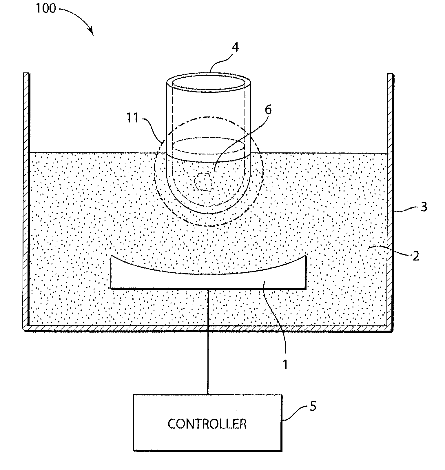
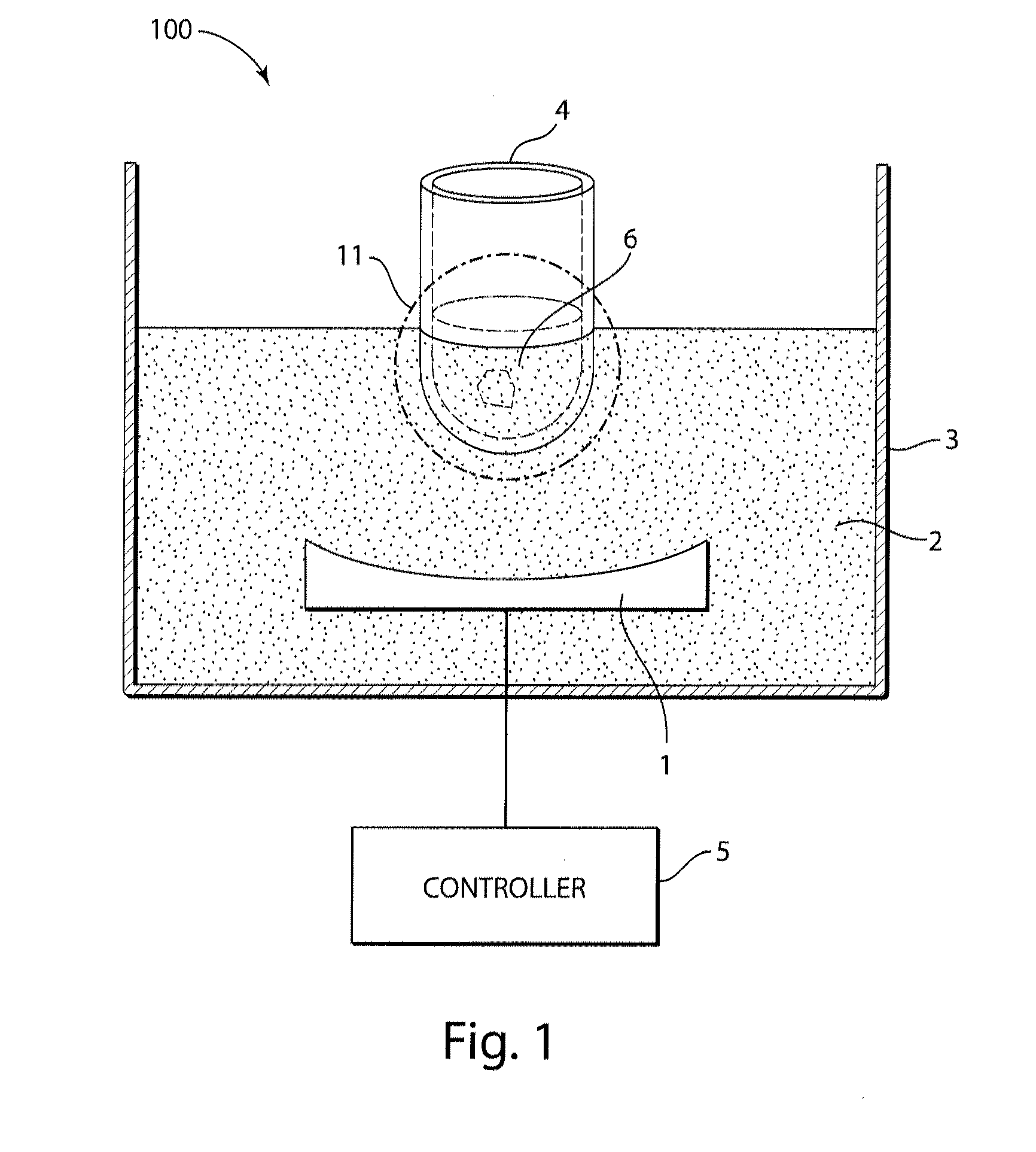
[0019]Although aspects of the invention are described with reference to embodiments in which acoustic energy is used to heat and / or cool a sample, the sample may be subjected to other treatments or other processes by the acoustic energy. For example, the acoustic energy may also be suitable, or be adjusted, to cause other effects in the liquid, such as fluidizing the sample, mixing the sample, stirring the sample, catalyzing the sample, disrupting the sample (such as shearing or fragmenting DNA molecules or other compounds, lysing cells, etc.), permeabilizing a component of the sample, enhancing a reaction in the sample (such as binding of material to the material supports), causing crystal growth in the sample (e.g., by nucleating crystal growth sites and / or enhancing the rate of crystal growth), preparing formulations (e.g., suspensions and / or emulsions suitable for therapeutic use), causing flow in a conduit, and / or sterilizing the sample. Thus, the acoustic energy may be used fo...


PUM


Abstract

Methods and systems relate to enhancing heat transfer between a vessel wall and a sample or coupling medium during focused acoustic processing. The vessel containing the sample may include a heat exchanger on an inner surface and / or an outer surface of the vessel that can have any suitable shape or dimension that increases the surface area of the vessel wall. In some embodiments, heat exchanger features may disrupt a boundary layer of a liquid sample at the vessel wall during focused acoustic processing. Accordingly, the temperature of the liquid sample can be appropriately controlled. In some cases, heating and / or cooling of the liquid sample may be performed efficiently. In an embodiment, a liquid sample may be heated at a rate of at least about 25 degrees C. per ml per minute.

Description

RELATED APPLICATIONS[0001]This application claims the benefit of U.S. Provisional Application No. 61 / 368,410, filed Jul. 28, 2010, which is hereby incorporated by reference in its entirety.BACKGROUND[0002]1. Field of Invention[0003]Aspects described herein relate to acoustic treatment of samples, such as liquid material contained in a well of a microtiter plate or other similar vessel. In some cases, acoustic treatment of a sample may involve enhancing heat transfer between the vessel wall and the sample, such as through the disruption of a boundary layer at a vessel wall.[0004]2. Related Art[0005]Analytical techniques for biological and chemical samples often require an extreme physicochemical preparatory step to enable the desired analysis to be fully achieved. For example, extraction / digestion of herbicides and pesticides from plant tissue may require organic solvents (e.g., alcohols) and elevated temperatures (e.g., 50 degrees C.). This requirement to elevate the temperature of ...

Claims


Application Information

Patent Timeline
IPC IPC(8): B65D90/00F28F7/00
CPCF28F1/18F28F13/00F28F1/26
Inventor LAUGHARN, JR., JAMES A.
Owner COVARIS INC
Why Eureka
Try Eureka