Combined cycle power plant

Active Publication Date: 2010-05-06
GENERAL ELECTRIC CO
View PDF13 Cites 7 Cited by
  • Summary
  • Abstract
  • Description
  • Claims
  • Application Information

AI Technical Summary

Benefits of technology

[0004]A combined cycle power plant includes a gas turbine and a steam turbine that are thermally connected by a heat recovery steam generator. The heat recovery steam generator includes a duct for receiving and confining gas turbine exhaust gas from the gas turbine. Heat transfer tubes are disposed within the duct and have exte

Problems solved by technology

HRSGs typically utilize finned type tubes (solid and serrated) to enhance the rate of heat transfer from the gas turbine exhaust gas to the water/steam in the tube bundles however, overall heat trans

Method used


Image

  • Combined cycle power plant
  • Combined cycle power plant
  • Combined cycle power plant

Examples


Example

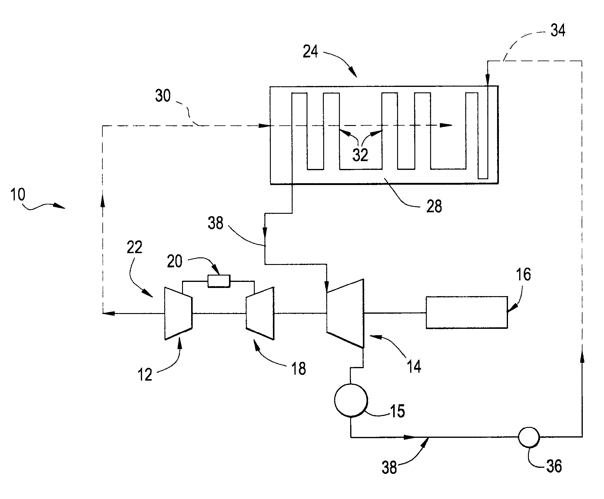
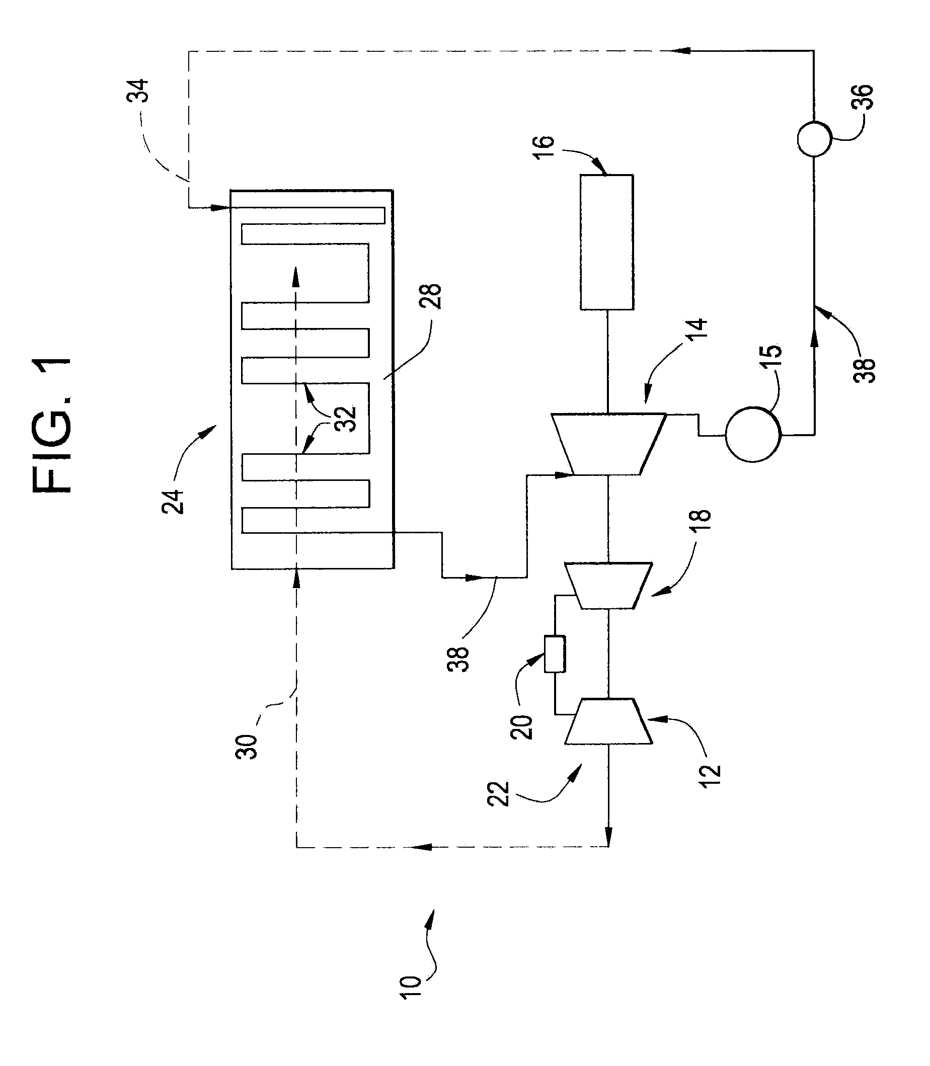
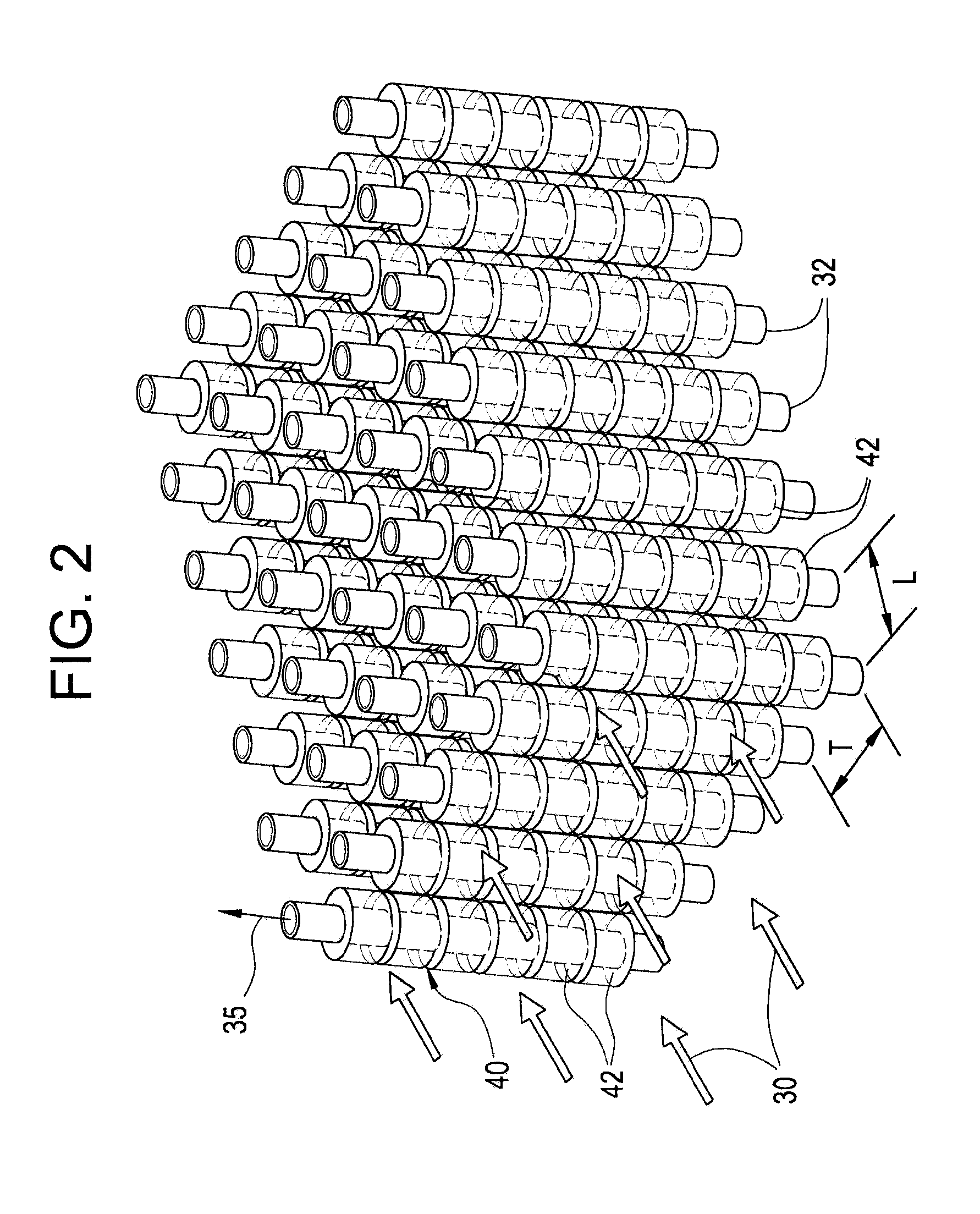
[0013]Referring now to the drawings, in which like numerals indicate like elements throughout the views, FIG. 1 shows an exemplary embodiment of a single shaft, combined cycle power plant 10. The combined cycle power plant includes a gas turbine system 12, a steam turbine system 14 and a generator 16 that is driven by the gas and steam turbines to generate electricity. The gas turbine system includes, in serial flow communication, a multistage axial compressor 18, a combustor 20, and a multi-stage turbine 22. The gas turbine system 12 and the steam turbine system 14 are thermally connected through HRSG 24. The HRSG 24 is a heat exchanger configured to include a duct 28 for receipt and confinement of gas turbine exhaust gas 30 exiting the multi-stage turbine 22. Bundles of heat transfer tubes 32 are disposed within the duct 28 of the HRSG 24 and are adapted to receive feed water 34 (condensate from steam turbine condenser 15) that is circulated through the tubes by the feed water pum...


PUM


Abstract

A combined cycle power plant includes at least one gas turbine, at least one steam turbine and a heat recovery boiler in combination to produce electricity and/or process steam. The heat recovery boiler has a duct for receiving and confining gas turbine exhaust gas from the gas turbine. Heat transfer tubes for heating water and steam for use in the bottoming steam cycle (steam turbine and/or process steam) are disposed within the heat recovery boiler and have exterior surfaces in fluid communication with the gas turbine exhaust gas and interior surfaces in circulatory fluid communication with water and/or steam. A cellular material is attached to the exterior surfaces of the heat transfer tubes and operates to enhance heat transfer from the gas turbine exhaust gas to the water and/or steam.

Description

BACKGROUND OF THE INVENTION[0001]The subject matter disclosed herein relates to a combined cycle power plant and, more particularly, to the heat recovery boiler with enhanced heat transfer surface area for improved combined cycle performance and economics. The subject matter applies to a single shaft, combined cycle power plant, a multi-shaft, combined cycle power plant and a cogeneration power plant. In addition the subject matter may be applicable to natural circulation, forced circulation and once through heat recovery boilers configured with horizontal and / or vertical heat transfer tubes with gas turbine exhaust flow in either a horizontal and / or vertical direction. The heat recovery boiler tube arrangement may be in-line or staggered and the heat recovery boiler may be unfired or supplementary fired.[0002]Combined cycle power plants utilize at least one gas turbine, at least one steam turbine and heat recovery boilers in combination to produce electricity and / or to process stea...

Claims


Application Information

Patent Timeline
IPC IPC(8): F01K23/08F02C6/00
CPCF01K23/10F02C6/18F28D7/1615F28F13/003Y02E20/14Y02E20/16F05D2220/31
Inventor HARDWICKE, CANAN USLULEONE, SAL ALBERTTAYLOR, THOMAS FRANCISZHANG, HUA
Owner GENERAL ELECTRIC CO
Why Eureka
Try Eureka