Device to enhance radiant transfer of heat from the earth to outer space

Active Publication Date: 2022-06-21
ADELMAN MICHAEL ROSS
View PDF2 Cites 0 Cited by
  • Summary
  • Abstract
  • Description
  • Claims
  • Application Information

AI Technical Summary

Benefits of technology

The invention is a device called a Radiant Energy Emitter Plate, which uses solar energy to generate heat. The invention aims to improve the transfer of heat from the device to outer space by maintaining a consistent surface temperature and reducing heat loss through conductation and convection. The device can be controlled and maintained using a battery and a controller, which uses a temperature sensing device to regulate the surface temperature. The highest temperature the device can reach is limited only by the battery's power capacity. The invention helps reduce heating in the atmosphere and can improve energy efficiency. It can be installed in remote locations without the need for externally produced power, providing a means to reduce heat on the planet.

Problems solved by technology

But the bulk of the heat, which is ultimately heating the earth, is coming from the release of heat during the combustion process of fossil fuels and the release of energy during the reactions of the nuclear fuels.
During power generation and other direct combustion of fossil fuels and production of nuclear power, there is an enormous amount of heat released directly into the environment.
This is not going away with either nuclear fission power generation or nuclear fusion power generation, if that ever becomes commercially viable.
And, of course, an enormous amount of heat is released from the fossil fuels burned directly for other purposes, such as direct heating, manufacturing, cars, airplanes and other forms of transportation.
Simply reducing the by-products of combustion will help to reduce CO2 release, but will not stop the immense quantity of heat energy released.
In engineering terms, the transfer of heat by radiant means is the most difficult to understand.

Method used


Image

  • Device to enhance radiant transfer of heat from the earth to outer space

Examples


Embodiment Construction

[0034]Of course, the preferred and many other embodiments may be fabricated by a person skilled in the art.

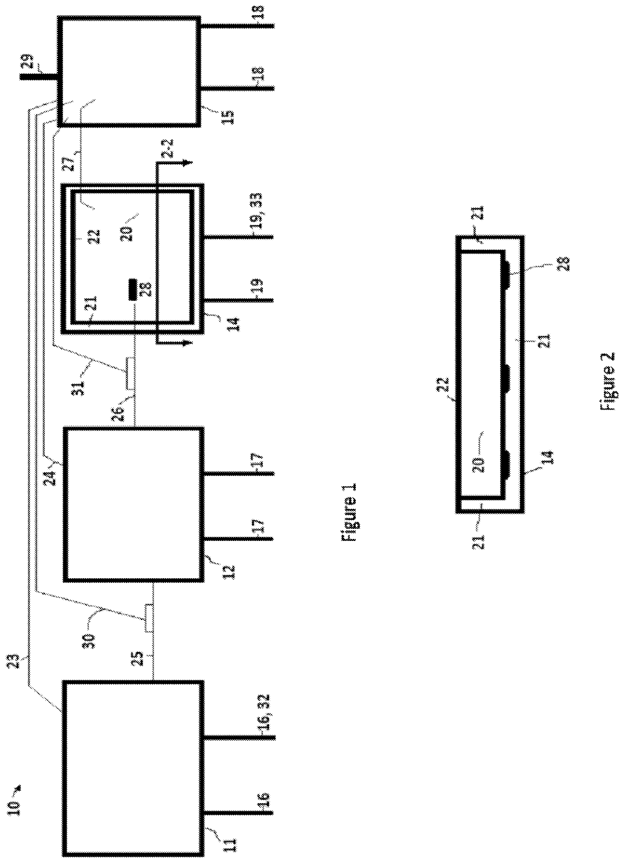
[0035]With reference to the drawings, a preferred embodiment of A Device to Enhance Radiant Transfer of Heat from the Earth to Outer Space is shown in FIG. 1. As illustrated, it generally comprises:[0036]10—The overall view of the invention being described[0037]11—Solar Energy Collector Panel[0038]12—Rechargeable Battery[0039]14—Emitter Enclosure[0040]15—Controller[0041]16—Support Leg[0042]17—Support Leg[0043]18—Support Leg[0044]19—Support Leg[0045]20—Emitter Radiant Heating Element[0046]21—Conductive Insulation[0047]22—Convective Insulation[0048]23—Solar Panel Sensor and Control Wire[0049]24—Rechargeable Battery Sensor and Control Wire[0050]25—Solar panel to Battery Charging Wire[0051]26—Rechargeable Battery to Emitter Heating Coil Wire[0052]27—Emitter Temperature Sensor[0053]28—Heating Coils[0054]29—Day / Night / Obstruction Sensor[0055]30—Solar Cell to Battery Charging Wire and ...


PUM


Abstract

A Device to Enhance Radiant Transfer of Heat from the Earth to Outer Space comprising a collector of energy from a renewable energy source, a storage device for the collected electrical energy in a rechargeable battery, a radiant energy emitter plate consisting of an enclosure with supports, radiant energy emitter plate, plate heating elements, insulating elements for reduction of heat loss via conduction from the enclosure and insulating elements for reduction of heat loss via convection from the enclosure, temperature sensor, and a controller device for regulating the connection and flow of gathered energy from the collector to the storage device to the radiant energy emitter plate.

Description

[0001]In an effort to reduce the CO2 present in the atmosphere so as to facilitate the resumption of outbound radiant transfer of heat energy, all sorts of schemes have been proposed. These include reducing the emission of CO2 during the power generation process associated with the Carbon contained within fossil fuels. It is the chemical reaction of the Carbon with Oxygen during the combustion process that releases the CO2. It is reported that the replacement of coal with natural gas as a fossil fuel reduces the CO2 emitted. CO2 is not released from nuclear power generation plants. CO2 is not released from Geo-thermal power generation plants.[0002]Other ideas for the reduction of CO2 have also been advanced such as CO2 sequestration. Ideas, such as placing an earth heat shield in space may prevent heat from entering the earth's atmosphere but would likely adversely prevent heat from transferring back out, something that should be approached very, very carefully.[0003]Another proposa...

Claims


Application Information

Patent Timeline
IPC IPC(8): F03D9/00H02S10/12F03D9/25F03D9/11F03D9/18
CPCF03D9/007H02S10/12F03D9/11F03D9/18F03D9/25Y02E10/50Y02E10/72Y02E70/30H02S40/42
Inventor ADELMAN, MICHAEL ROSS
Owner ADELMAN MICHAEL ROSS
Why Eureka
Try Eureka