Sputtering target temperature control utilizing layers having predetermined emissivity coefficients

Inactive Publication Date: 2011-01-13
GENERAL PLASMA
View PDF6 Cites 4 Cited by
  • Summary
  • Abstract
  • Description
  • Claims
  • Application Information

AI Technical Summary

Benefits of technology

[0013]A sputter coating apparatus for sputter coating a substrate in a processing chamber is provided that includes a target of sputter coating material supported within the processing chamber. The target has a sputtering surface and a back surface. The target is affixed to a backing plate such that the back surface of the target is disposed adjacent to a first surface of the backing plate. The backing plate is in fluid communication with a source of cooling fluid. The target back surface has a first layer selected to have a

Problems solved by technology

A heat transference limitation is that the surface of the target is not in complete contact with the mating surface of the backing plate.
Also, sputtering operation occurs in a vacuum; and with no

Method used


Image

  • Sputtering target temperature control utilizing layers having predetermined emissivity coefficients
  • Sputtering target temperature control utilizing layers having predetermined emissivity coefficients
  • Sputtering target temperature control utilizing layers having predetermined emissivity coefficients

Examples


Example

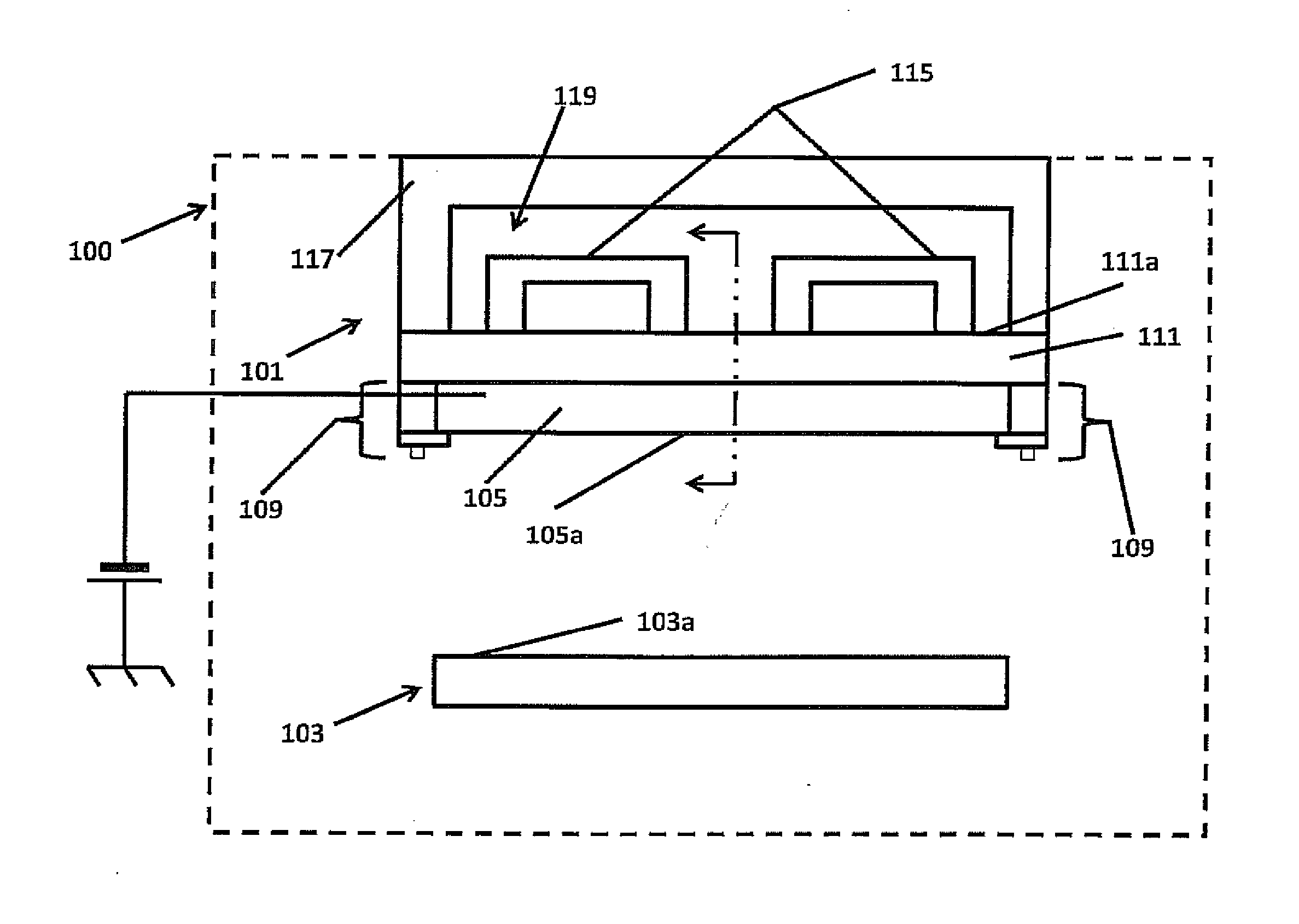
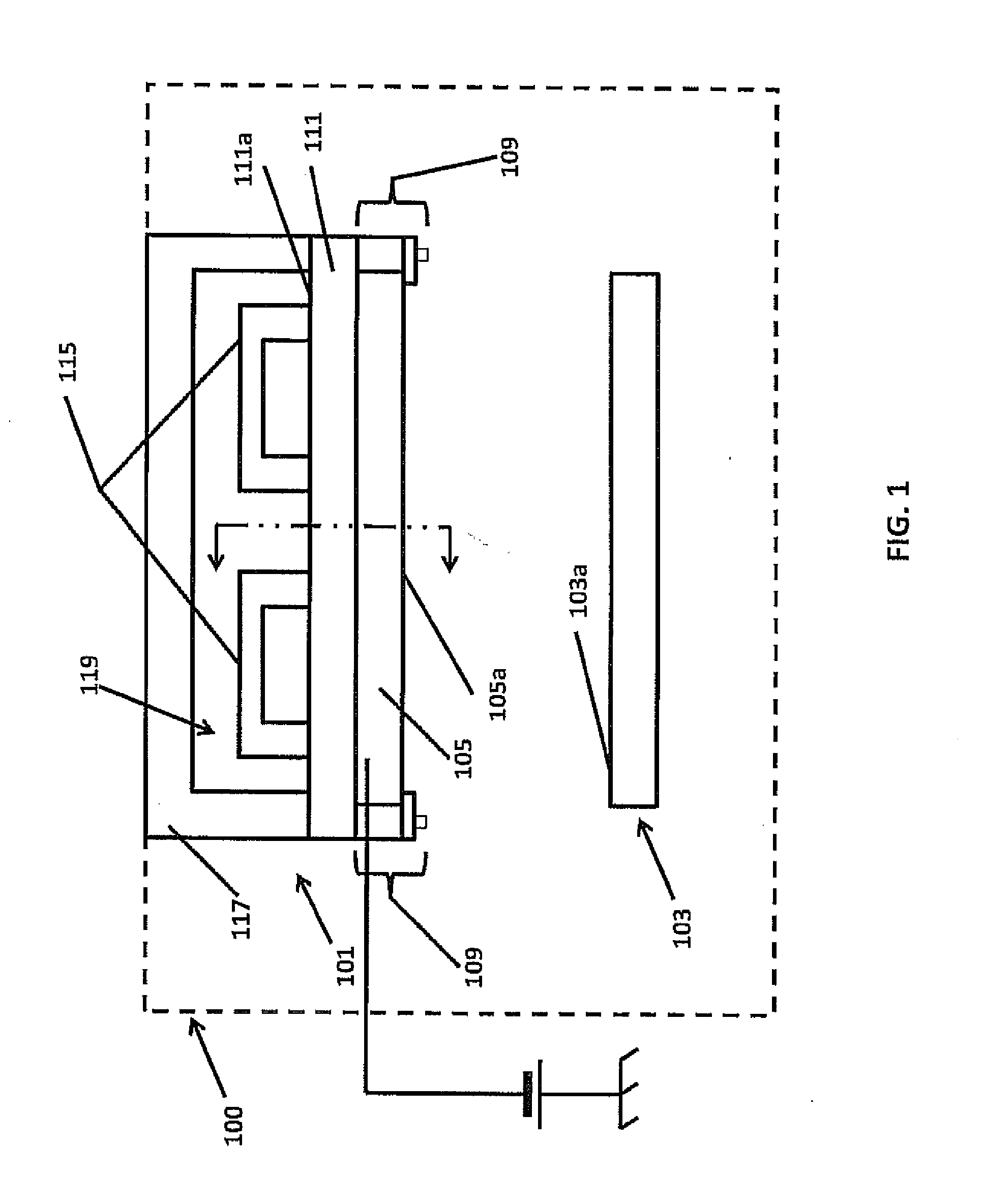
[0025]The present invention has utility as a sputtering assembly with improved thermal management characteristics. The prior sputtering assemblies rely upon the fundamental principle that conduction is the most significant means of heat transfer in a solid. Because the target back surface is typically machined and polished and the backing plate mating surface is also machined and polished and the target is clamped or bolted to the backing plate, it is typically assumed that heat transference between the target and the backing plate occurs as a result of conduction or in some instances by conduction where the surface are in direct contact and by convection where the surfaces are separated.

[0026]The present invention is based on the surprising discovery that this conventional wisdom is incorrect and instead that the primary conductive transfer between a target and the backing plate occurs through the bolts that clamp the target to the backing plate because there is no assurance that t...


PUM

PropertyMeasurementUnit
Electrical conductoraaaaaaaaaa
Emissivityaaaaaaaaaa

Abstract

A sputter coating apparatus for sputter coating a substrate in a processing chamber includes a target of sputter coating material supported within the processing chamber. The target has a sputtering surface and a back surface. The target is affixed to a backing plate such that the back surface of the target is disposed adjacent to a first surface of the backing plate. The backing plate is in fluid communication with a source of cooling fluid. The target back surface has a first layer selected to have a high thermal emissivity coefficient. The backing plate first surface carries a second layer having a high emissivity coefficient. The target back surface first layer and the backing plate first surface second layer provide enhanced heat transfer between the target and the backing plate via thermal radiation.

Description

CROSS-REFERENCE TO RELATED APPLICATION[0001]This application claims priority of U.S. Provisional Patent Application Ser. No. 61 / 215,759 filed May 8, 2009, which is incorporated herein by reference.FIELD OF THE INVENTION[0002]The present invention relates in general to sputtering apparatus and methodology, and in particular to heat dissipation for a target in a sputtering apparatus.BACKGROUND OF THE INVENTION[0003]In a sputtering process, substrates that are to be sputter coated with a thin deposited film are positioned within a processing chamber adjacent to a sputtering target that is the source of the deposition material. The processing chamber is evacuated to provide a vacuum and the target has a negative voltage applied thereto. A plasma discharge is produced which creates positive ions that bombard the target separating atoms from the surface of the target. The atoms of target material travel to the substrate surface forming a coating of target material.[0004]Targets are typica...

Claims


Application Information

Patent Timeline
IPC IPC(8): C23C14/35C23C14/06
CPCC23C14/085C23C14/3407H01J37/3497H01J37/3426H01J37/3435H01J37/3408
Inventor MADOCKS, JOHNGEORGE, MARK A.
Owner GENERAL PLASMA
Why Eureka
Try Eureka