Light emitting diode having distributed bragg reflector

Active Publication Date: 2012-02-02
SEOUL VIOSYS CO LTD
View PDF6 Cites 78 Cited by
  • Summary
  • Abstract
  • Description
  • Claims
  • Application Information

AI Technical Summary

Benefits of technology

[0015]Exemplary embodiments of the present invention provide an LED to improve light emission efficiency of an LED package.
[0016]Exemplary embodiments of the present invention provide an LED to prevent op

Problems solved by technology

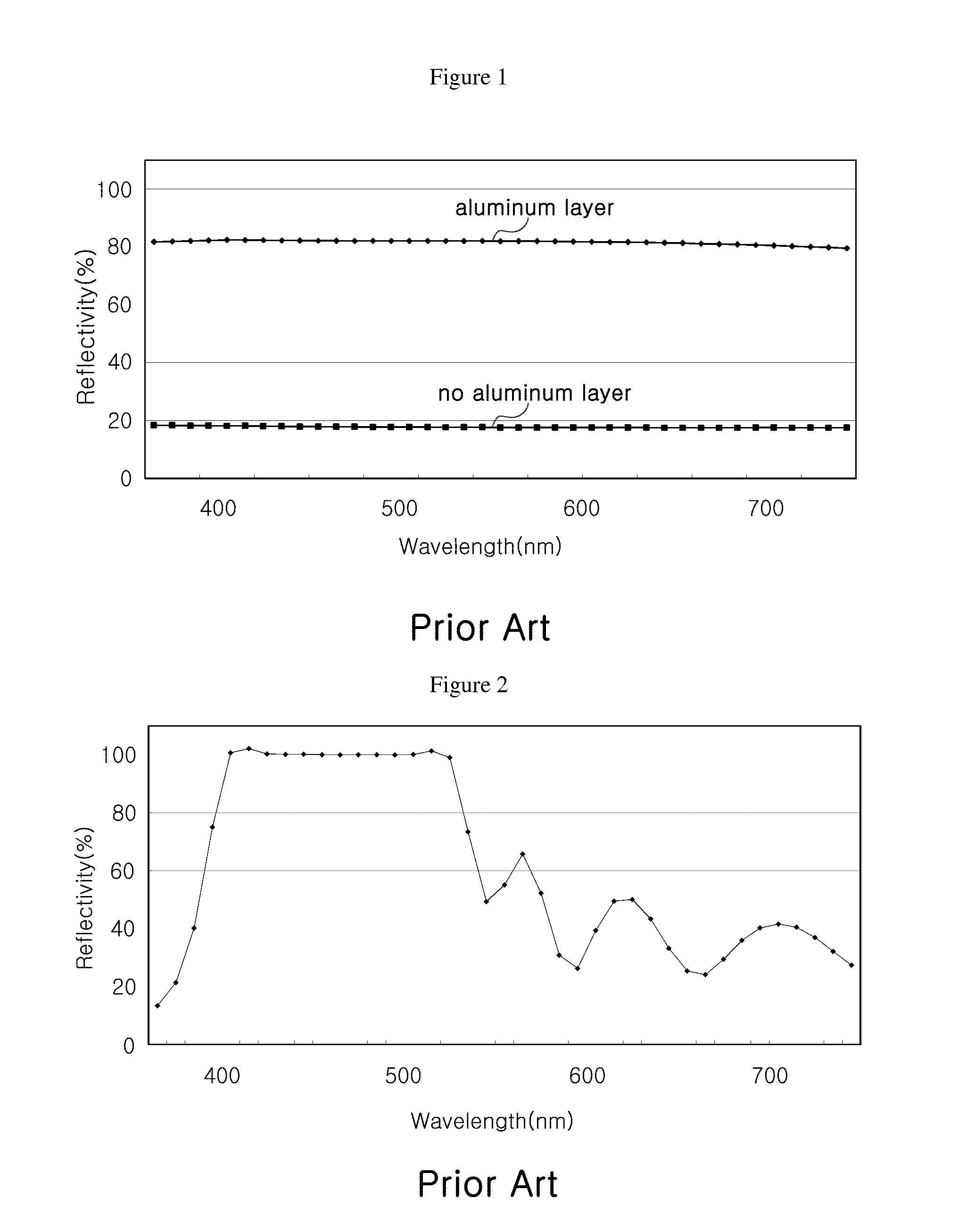
However, the distributed Bragg reflector may only increase reflectivity in certain regions of the visible spectrum and may exhibit significantly lower reflectivity in other regions.
Accordingly, when an LED with the distributed Bragg reflector is mounted on an LED package for emitting white light, the distributed Bragg reflector of

Method used


Image

  • Light emitting diode having distributed bragg reflector
  • Light emitting diode having distributed bragg reflector
  • Light emitting diode having distributed bragg reflector

Examples


Embodiment Construction

[0036]The invention is described more fully hereinafter with reference to the accompanying drawings, in which exemplary embodiments of the invention are shown. This invention may, however, be embodied in many different forms and should not be construed as limited to the exemplary embodiments set forth herein. Rather, these exemplary embodiments are provided so that this disclosure is thorough and will fully convey the scope of the invention to those skilled in the art. In the drawings, the sizes and relative sizes of layers and regions may be exaggerated for clarity. Like reference numerals in the drawings denote like elements.

[0037]It will be understood that when an element such as a layer, film, region or is substrate is referred to as being “on” another element, it can be directly on the other element or intervening elements may also be present. In contrast, when an element is referred to as being “directly on” another element, there are no intervening elements present.

[0038]FIG....


PUM


Abstract

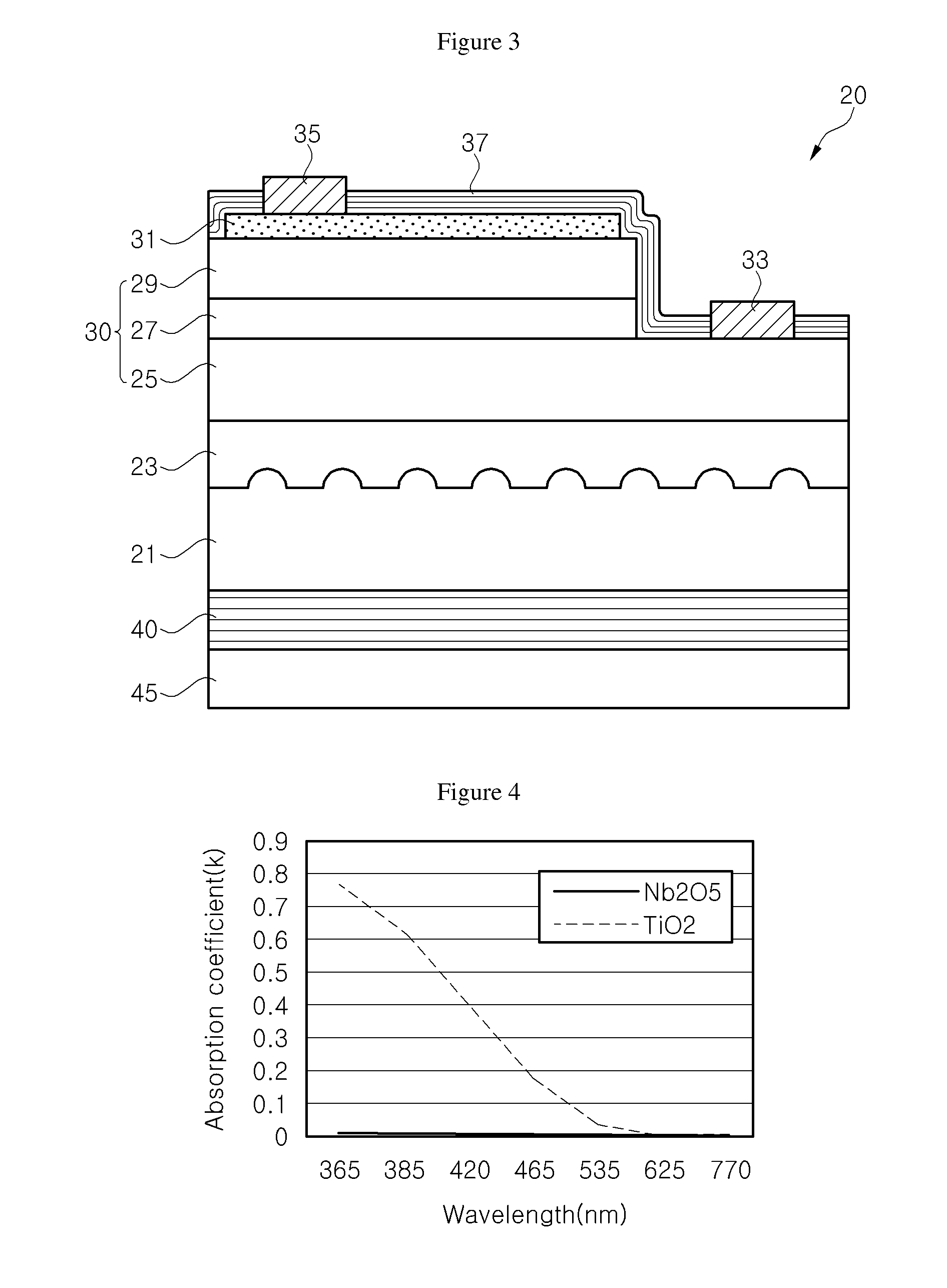
Exemplary embodiments of the present invention provide light-emitting diodes having a distributed Bragg reflector. A light-emitting diode (LED) according to an exemplary embodiment includes a light-emitting structure arranged on a first surface of a substrate, the light-emitting structure including a first conductivity-type semiconductor layer, a second conductivity-type semiconductor layer, and an active layer interposed between the first conductivity-type semiconductor layer and the second conductivity-type semiconductor layer. A first distributed Bragg reflector is arranged on a second surface of the substrate opposite to the first surface, the first distributed Bragg reflector to reflect light emitted from the light-emitting structure. The first distributed Bragg reflector has a reflectivity of at least 90% with respect to light of a first wavelength in a blue wavelength range, light of a second wavelength in a green wavelength range, and light of a third wavelength in a red wavelength range. The first distributed Bragg reflector has a laminate structure having an alternately stacked SiO2 layer and Nb2O5 layer.

Description

CROSS-REFERENCE TO RELATED APPLICATIONS[0001]This application claims priority from and the benefit of Korean Patent Application No. 10-2010-0072822, filed on Jul. 28, 2010, and Korean Patent Application No. 10-2010-0076914, filed on Aug. 10, 2010, which are hereby incorporated by reference for all purposes as if fully set forth herein.BACKGROUND OF THE INVENTION[0002]1. Field of the Invention[0003]Exemplary embodiments of the present invention relate to a light-emitting diode and, more particularly, to a light-emitting diode having a distributed Bragg reflector.[0004]2. Discussion of the Background[0005]Gallium nitride (GaN)-based blue or ultraviolet (UV) light-emitting diodes (LEDs) may be used in a wide range of applications. In particular, various kinds of LED packages for emitting light having mixed colors, for example, white light, have been applied to backlight units, general lighting devices, and the like.[0006]Since optical power of the LED package may depend upon luminous e...

Claims


Application Information

Patent Timeline
IPC IPC(8): H01L33/58
CPCH01L33/46H01L2924/181H01L2224/48091H01L2224/48247H01L2224/48257H01L2224/73265H01L2924/00012H01L2924/00014H01L33/10H01L33/50H01L33/38H01L33/42
Inventor SUH, DUK ILKIM, JAE MOOKIM, KYOUNG WANYOON, YEO JINKIM, YE SEULOH, SANG HYUNLEE, JIN WOONG
Owner SEOUL VIOSYS CO LTD
Why Eureka
Try Eureka