Projection type image display device

a technology of projection and display device, which is applied in the direction of projectors, optics, instruments, etc., can solve the problems of shortening the service life, increasing the number of crystal defects, and deteriorating light emission efficiency, so as to reduce the size of refrigerating means and reduce manufacturing costs and electric power costs

Active Publication Date: 2009-04-02
SANYO ELECTRIC CO LTD
View PDF8 Cites 35 Cited by
  • Summary
  • Abstract
  • Description
  • Claims
  • Application Information

AI Technical Summary

Benefits of technology

[0019]According to the present invention, since light source elements relatively large in the amount of heat generated are connected to the refrigerating means and the other light source arrays are connected to the auxiliary cooling means, it becomes possible to decrease the size o...

Problems solved by technology

However, in the case of a semiconductor laser, as the temperature rises, the light emission efficiency is deteriorated and the number of crystal defects increases.
Therefore, heat is generated also in a transition mechanism which operates as the original emission principle, so that the laser temperature rises and the light emitting capacity is deteriorated in an accelerated manner, thus leading to shortening of the service life.
In this state, the white balance is lost and it becomes impossible to make an accurate color gradation representation.
However, the cooling means disclosed in Japanese Patent Laid-Open Publication No. 2007-201285 uses a combined structur...

Method used


Image

  • Projection type image display device
  • Projection type image display device
  • Projection type image display device

Examples


Embodiment Construction

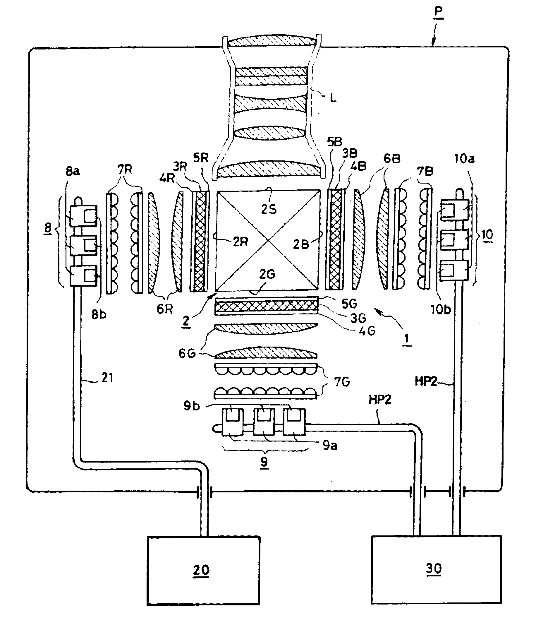
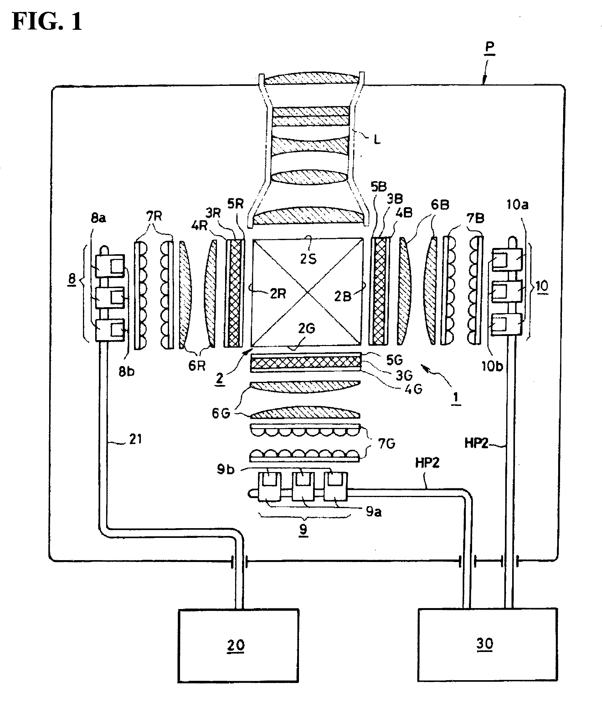
[0025]An embodiment of the present invention will be described in detail hereinbelow with reference to the accompanying drawings. FIG. 1 is a plan view showing a structure of a light source unit according to the present invention, FIG. 2 shows an assembled state thereof, FIGS. 3 and 4 are perspective views showing structures of principal portions of the light source unit according to the present invention, and FIG. 5 shows an example of refrigerating means and auxiliary cooling means used in the present invention.

[0026]FIG. 1 is a plan view showing a structure of a light source unit 1 as a principal portion of a projection type image display device P according to the present invention, in which irradiation surfaces 2R, 2G and 2B for laser beams of three primary colors are formed respectively on three side faces of a synthesizing prism 2 disposed centrally. Red color laser light, green laser light and blue laser light are radiated to the irradiation surfaces 2R, 2G and 2B, respective...


PUM


Abstract

There is provided a projection type image display device capable of simplifying cooling of light source elements of light source arrays, thereby reducing the size of refrigerating means, dispensing with complicated temperature adjustment and reducing the manufacturing cost and the electric power cost. The projection type image display device can attain projection light by modulating light beams of at least three primary colors in accordance with image information and synthesizing the modulated light beams. The projection type image display device comprises a light source unit constituted by arranging a plurality of light source elements hierarchically so as to conduct the light beams of the colors to irradiation surfaces of a synthesizing prism, the light source elements comprising light source arrays each of plural light emitting elements arranged on one and same substrate, the light source arrays being arranged on heat receiving plates respectively; refrigerating means including at least a refrigerant compressor, a condenser, a pressure reducing device and a refrigerant pipe constituting an evaporator; and auxiliary cooling means lower in cooling capacity than the refrigerating means. Of the plural light source arrays, those relatively large in the amount of heat generated are connected to the refrigerating means, while the others are connected to the auxiliary cooling means.

Description

BACKGROUND OF THE INVENTION[0001]1. Field of the Invention[0002]The present invention relates to an improvement of a light source unit adopting light source arrays in a projection type image display device (projector) which is for modulating light beams of three primary colors in accordance with image information, synthesizing the modulated light beams to generate projection light and projecting an image onto a screen through a projection lens.[0003]2. Description of the Related Art[0004]In many conventional projection type image display devices, a discharge lamp such as a metal halide lamp or an ultra-high pressure mercury lamp is adopted as a light source for generating light beams of three primary colors. In case of using a so-called 3-CCD, white light emitted from a discharge lamp is separated into the three primary colors of red (R), green (G) and blue (B) by means of a dichroic mirror, and then the three primary colors are modulated in accordance with image information and syn...

Claims


Application Information

Patent Timeline
IPC IPC(8): G03B21/00
CPCG03B21/00G03B21/006
Inventor NAKAMURA, TAKAHIRO
Owner SANYO ELECTRIC CO LTD
Why Eureka
Try Eureka