Power conversion device

a power conversion device and power technology, applied in the direction of conversion with intermediate conversion to dc, electric power transfer ac network, active power filtering, etc., can solve the problems of large reactor, inability to always and completely match the voltage of three legs, and the requirement of reactors for each leg, etc., to achieve the effect of reducing size and weigh

Inactive Publication Date: 2012-02-02
HITACHI LTD
View PDF1 Cites 101 Cited by
  • Summary
  • Abstract
  • Description
  • Claims
  • Application Information

AI Technical Summary

Benefits of technology

[0074]According to the present invention, there is provided a power conversion device which can eliminate a reactor and is reduced in size and weight.
[0075]In addition, in the power conversion device of the present invention, a zero-phase DC current flows in the secondary winding of the transformer when the power conversion device transmits and receives active power to and from a power system. However, since a magnetomo

Problems solved by technology

However, there are two problems in MMC described later.
The first problem is that a reactor is required for each leg.
When the voltage VC of the energy storage device is different for each leg, it is impossible to alway

Method used


Image

  • Power conversion device
  • Power conversion device
  • Power conversion device

Examples


first embodiment

[0116]An explanation will given of a first embodiment embodying the present invention.

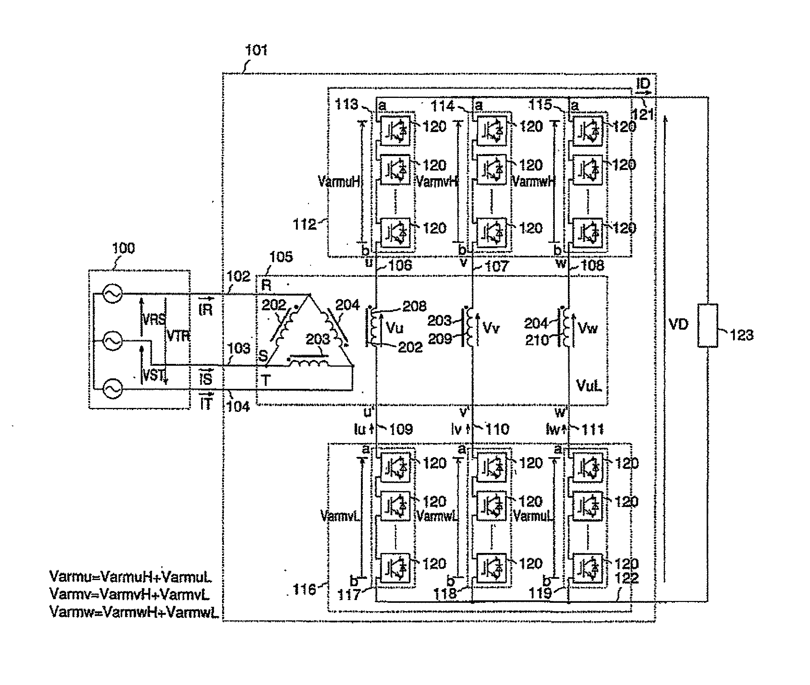
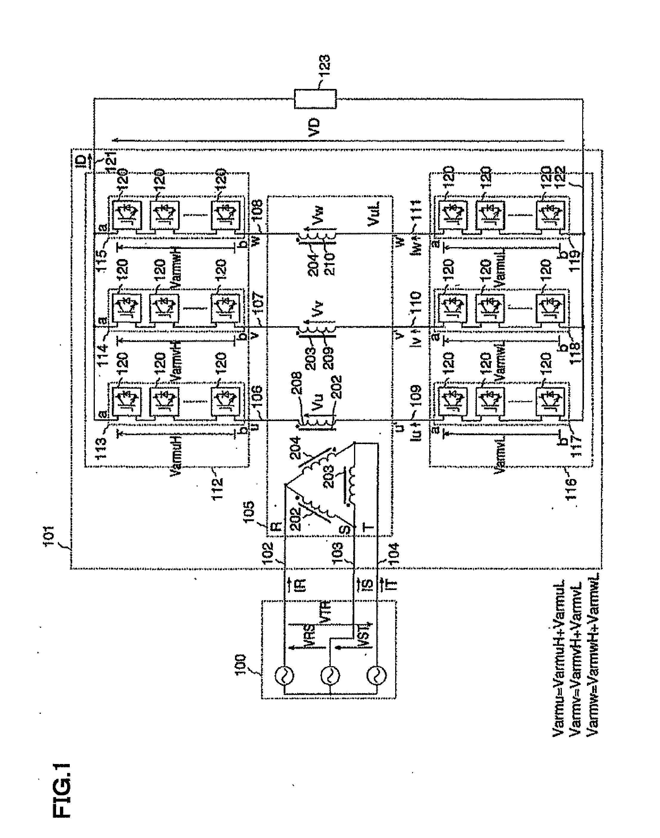
[0117]A configuration of a power conversion device 101 according to the present invention will be explained using FIG. 1.

[0118]The power conversion device 101 consists of a transformer 105, a positive converter group 112 and a negative converter group 116.

[0119]In the present embodiment, each phase of a three-phase power system 100 is called an R-phase, an S-phase and a T-phase. In addition, line voltages are denoted by VRS, VST and VTR, respectively. Furthermore, a current flowing in each phase of the three-phase power system 100 is called a system current and denoted by IR, IS and IT.

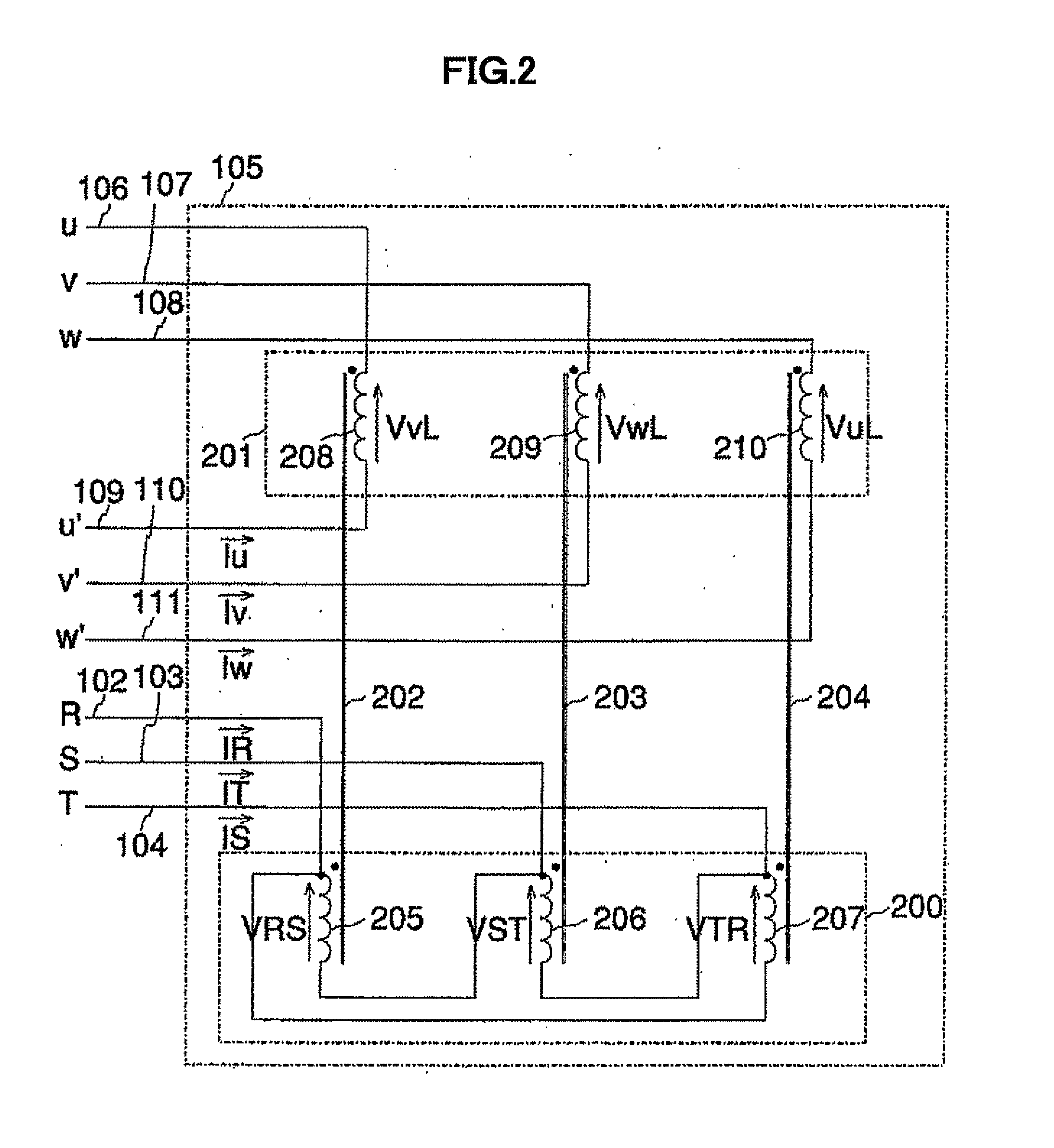
[0120]Next, a configuration of the transformer 105 will be explained using FIG. 1 and FIG. 2.

[0121]The transformer 105 includes nine terminals in total that are an R-phase terminal 102, an S-phase terminal 103, a T-phase terminal 104, a u-phase positive terminal 106, a v-phase positive terminal 107, a w-phase positiv...

second embodiment

[0192]An explanation will be given of a second embodiment of the present invention. In the first embodiment, the primary winding of the transformer was delta-connected. However, in the second embodiment, the primary winding of the transformer is star-connected.

[0193]Hereinafter, the explanation will be given of only a part of configuration of the second embodiment different from the first embodiment.

[0194]FIG. 6 is a circuit diagram showing the second embodiment of the present invention. A power conversion device 600 is interconnected with the three-phase power system 100 through three-phase AC terminals 102 to 104, and transmits and receives active / reactive power to and from the three-phase power system 100. The power conversion device 600 consists of a transformer 601, a positive converter group 112 and a negative converter group 116 different.

[0195]In the embodiment, phase voltages of the R-phase, the S-phase and the T-phase of the three-phase power system 100 are denoted by VR, ...

third embodiment

[0199]An explanation will be given of a third embodiment embodying the present invention. The third embodiment is a modification of the first embodiment. In the first embodiment, two converter groups that are on the positive side and the negative side are used. However, in the third embodiment, only one converter group is used.

[0200]In the third embodiment, the number of terminal of the transformer can be reduced from nine terminals to seven terminals, while effects identical to those of the first embodiment can be obtained.

[0201]Below, an explanation will be given of only a part of configuration of the third embodiment different from the first embodiment.

[0202]FIG. 8 is a circuit diagram showing a third embodiment of the present invention. A power conversion device 800 is interconnected with the three-phase power system 100 through three-phase AC terminals 102 to 104, and transmits and receives active / reactive power to and from the three-phase power system 100. The power conversion...


PUM


Abstract

A power conversion device connected with a three-phase power system through a transformer, including unit converters cascade-connected so that reactors are unnecessary, and volume and weight are reduced. The secondary winding of the transformer is an open winding having six terminals. A first converter group, includes a circuit which has three converter arms, which are star-connected, connected to three of the terminals of the secondary winding. A second converter group, having three different converter arms which are star-connected, is connected to three other terminals of the secondary winding. A neutral point (the point where the star connection is made) of the first converter group, and a neutral point of the second converter group are made to be the output terminals of the power conversion device.

Description

TECHNICAL FIELD[0001]The present invention relates to a power conversion device, and more particularly to the power conversion device interconnected with a three-phase system through a transformer and a DC transmission system using the power conversion system.BACKGROUND ART[0002]A non-patent document 1 listed below proposes a modular multilevel converter (MMC) by using a switching device (for example, IGBT: Insulated-gate bipolar transistor) capable of ON / OFF control, as a method of a power conversion device which can output a high voltage higher than a breakdown voltage of the switching device.[0003]First, a name of each part of MMC is defined in order to explain a circuit configuration of MMC.[0004]In MMC, a bidirectional chopper circuit shown in FIG. 4 forms a unit converter.[0005]Each unit converter is connected to an external circuit through at least two terminals. In the present embodiment, the two terminals are called an x-terminal and a y-terminal, respectively. In addition,...

Claims


Application Information

Patent Timeline
IPC IPC(8): H02M7/04H02M7/00
CPCH02J3/1857H02J3/36H02M7/217Y02E40/26Y02E60/60H02M7/219H02M2007/4835H02M7/5388H01F27/42Y02E40/20H02M7/4835H02M1/0009H02M1/08H02M7/797
Inventor INOUE, SHIGENORIKATOH, SHUJINARUSHIMA, JUNKATO, TETSUYA
Owner HITACHI LTD
Why Eureka
Try Eureka