
Grinding method and grinding machine

a grinding machine and grinding method technology, applied in the field of grinding operation control, can solve the problems of difficult suppression of a distance change, error, and change in the outside diameter of the grinding wheel, and achieve the effect of reducing idle grinding time, accurate calculation, and improving efficiency

Active Publication Date: 2012-02-02
JTEKT CORP
View PDF6 Cites 10 Cited by
  • Summary
  • Abstract
  • Description
  • Claims
  • Application Information

AI Technical Summary

Benefits of technology

[0007]The invention is made in light of the above-described circumstances, and it is an object of the invention to provide a grinding method and a grinding machine that make it possible to measure the outside diameter of a grinding wheel in a short period of time with a simple configuration even during grinding or truing, thereby improving the rate of operation of the grinding machine at low cost.
[0009]A reduction amount of the grinding wheel diameter is measured on the basis of a sonic velocity in the grinding layer and a difference between an arrival time difference between a reflected wave from a surface of the grinding layer before the grinding wheel diameter is reduced and a reflected wave from a surface of the outer periphery of the core and an arrival time difference between a reflected wave from a surface of the grinding layer after the grinding wheel diameter is reduced and a reflected wave from the surface of the outer periphery of the core, so it is possible to measure an accurate grinding wheel outside diameter that is not influenced by changes in distance between an ultrasonic head and a grinding wheel. In addition, the grinding wheel outside diameter may be measured in a state where grinding fluid adheres to the surface of the grinding wheel, so the outside diameter of the grinding wheel may be measured even during truing or immediately after truing. Therefore, a time required to measure the outside diameter of a grinding wheel is reduced to thereby make it possible to reduce a decrease in the rate of operation of the grinding machine.
[0012]A removed component that constitutes the grinding layer is determined, and the removal amount may be accurately calculated using the sonic velocity in the removed component, so it is possible to measure an accurate grinding wheel outside diameter.
[0013]According to another feature of the invention, by way of example, the outside diameter of the grinding wheel is measured while the workpiece is being ground, and the grinding operation is controlled using an amount of change in the outside diameter of the grinding wheel as an amount of wear of the grinding wheel due to grinding. The outside diameter of the grinding wheel is measured in a short period of time during grinding, and the measured outside diameter of the grinding wheel is used to change a grinding start position of the grinding wheel or to evaluate the amount of wear of the grinding wheel to thereby determine whether to carry out truing. Thus, it is possible to reduce an idle grinding time or carry out truing after a grinding wheel is used until its service life limit, so it is possible to improve efficiency and reduce grinding cost.
[0014]Further by way of example, according to another aspect of the invention, the outside diameter of the grinding wheel is measured while the grinding wheel is being trued, and the truing operation is controlled using an amount of change in the outside diameter of the grinding wheel as a removal amount of the grinding wheel due to truing. An amount of change in the outside diameter of the grinding wheel may be continuously measured during truing, so it is possible to accurately control truing operation that is based on an actual removal amount of the grinding wheel and that does not require unnecessary removal of grinding wheel, so it is possible to reduce grinding cost.

Problems solved by technology

During grinding, the outside diameter of a grinding wheel changes due to wear of the grinding wheel caused by grinding or a repair of a grinding layer of the grinding wheel.
As a result, an error may be caused.
Particularly, it is difficult to suppress a change in the distance due to the thermal expansion of a component resulting from a temperature change.
However, an expensive material or a temperature controller is required.

Method used


Image

  • Grinding method and grinding machine
  • Grinding method and grinding machine
  • Grinding method and grinding machine

Examples


Embodiment Construction

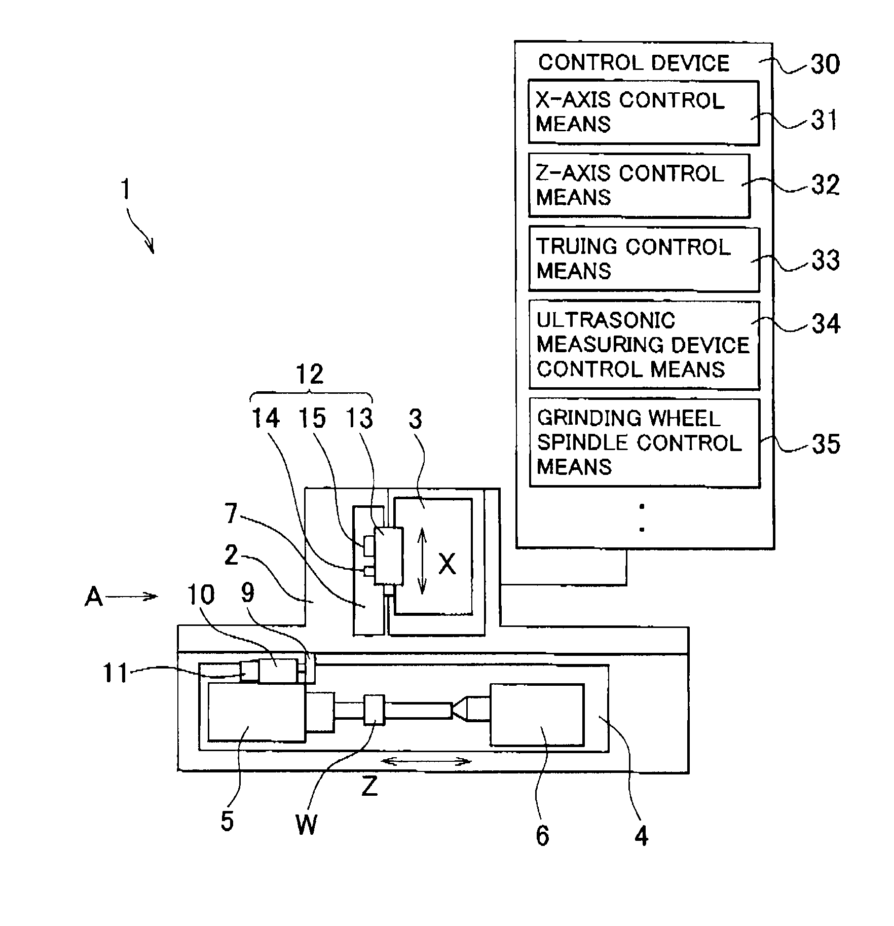
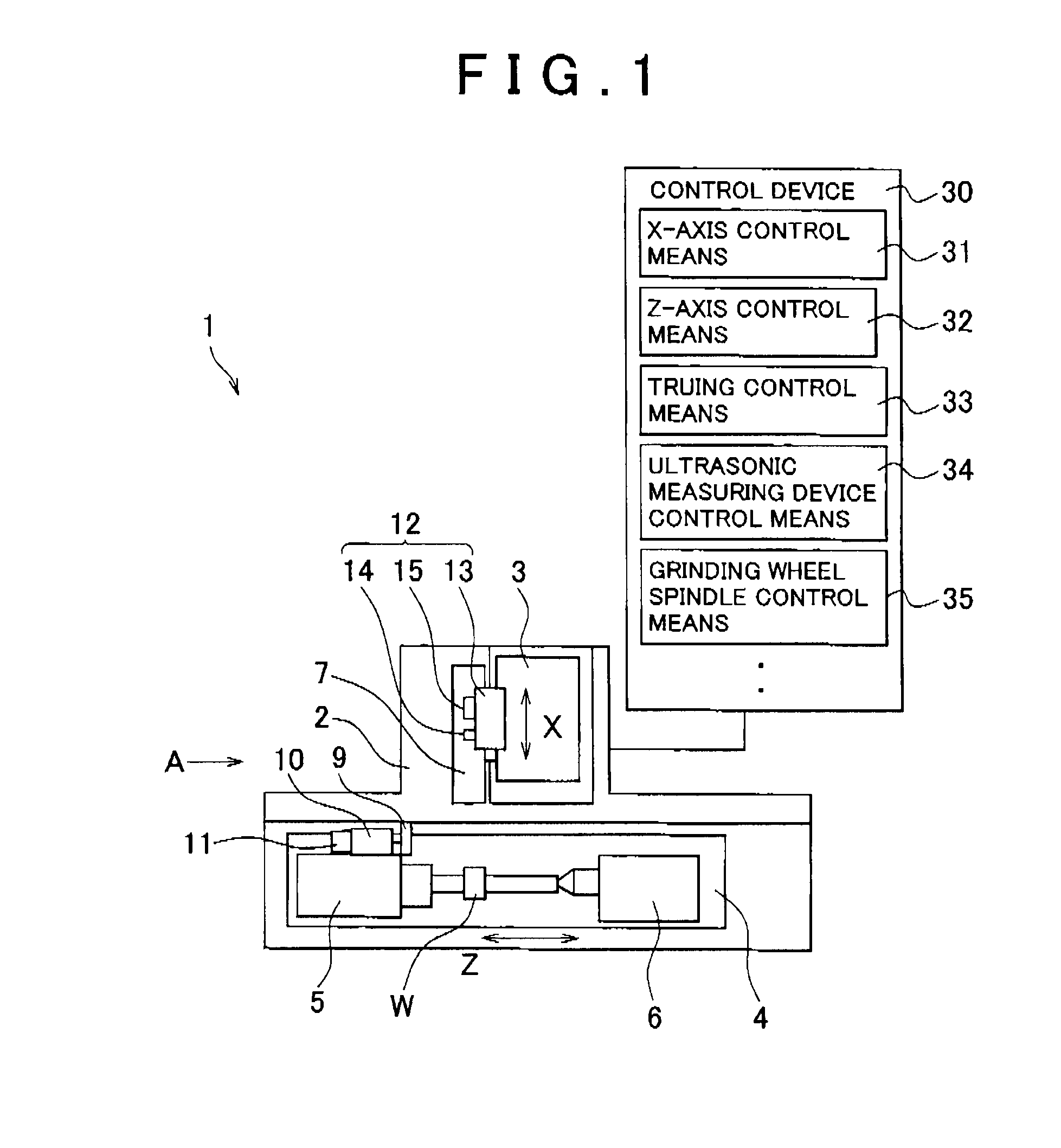
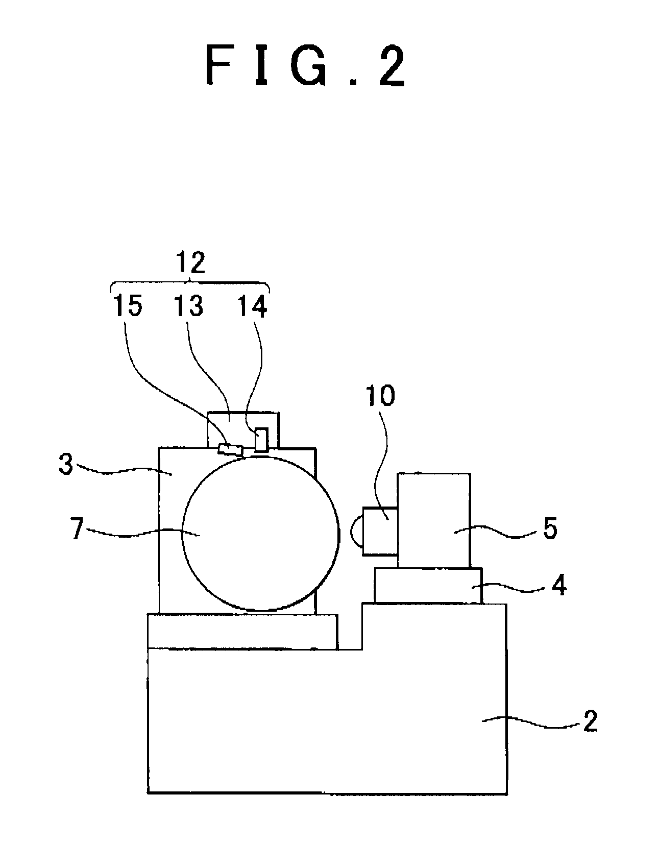
[0027]Hereinafter, a grinding process and a truing process that include a grinding wheel diameter measuring process performed using an ultrasonic measuring device according to an embodiment of the invention will be described on the basis of an example embodiment of an external cylindrical grinding machine with reference to FIG. 1 to FIG. 11.

[0028]As shown in FIG. 1 and FIG. 2, a grinding machine 1 includes a bed 2, and includes a grinding wheel head 3 and a table 4 placed on the bed 2. The grinding wheel head 3 is able to reciprocate in the X-axis direction. The table 4 is able to reciprocate in the Z-axis direction that is perpendicular to the X-axis direction. The grinding wheel head 3 rotatably supports a grinding wheel 7, and includes a grinding wheel spindle motor (not shown) that rotates the grinding wheel 7. The grinding wheel spindle motor is provided with a phase detector (not shown). The phase detector measures the rotational phase of the grinding wheel 7. As shown in FIG....


PUM

PropertyMeasurementUnit
Diameteraaaaaaaaaa
Velocityaaaaaaaaaa

Abstract

A core grinding wheel that has a grinding layer on an outer periphery of a core is used. An ultrasonic wave is output from an ultrasonic sensor to the grinding layer via grinding fluid. An ultrasonic measuring device control unit calculates a thickness of the grinding layer on the basis of a sonic velocity in the grinding layer and an arrival time difference between a reflected wave from a surface of the grinding layer and a reflected wave from a surface of the outer periphery of the core. A grinding process and a truing process are controlled on the basis of an outside diameter of the grinding wheel, which is calculated on the basis of the measured thickness of the grinding layer and an outside diameter of the core.

Description

INCORPORATION BY REFERENCE / RELATED APPLICATION[0001]This application claims priority to Japanese Patent Application No. 2010-168011 filed on Jul. 27, 2010 the disclosure of which, including the specification, drawings and abstract, is incorporated herein by reference in its entirety.BACKGROUND OF THE INVENTION[0002]1. Field of the Invention[0003]The invention relates to a grinding operation control and, more particularly to a grinding method and grinding machine with which a change in the outside diameter of a grinding wheel during grinding is measured to control a grinding operation.[0004]2. Discussion of Background[0005]During grinding, the outside diameter of a grinding wheel changes due to wear of the grinding wheel caused by grinding or a repair of a grinding layer of the grinding wheel. Detecting the amount of change in the outside diameter to control a grinding operation based on the detected change amount is indispensable for improving grinding accuracy and grinding efficien...

Claims


Application Information

Patent Timeline
IPC IPC(8): B24B49/00
CPCB24B1/00B24B5/02B24B49/003G05B2219/37269B24B49/18B24B53/053G05B19/4163B24B49/045
Inventor TANO, MAKOTOWAKAZONO, YOSHIO
Owner JTEKT CORP
Learn More