Vehicle body attitude control apparatus

a technology of vehicle body and attitude control, which is applied in the direction of process and machine control, cycle equipment, instruments, etc., can solve the problems of inability to solve bad feelings, other related technologies also have problems, and the control of the brake cannot avoid excessive slowdown of the vehicle, so as to improve the operability of cornering and improve steering stability, the effect of improving ride comfor

Active Publication Date: 2012-02-02
HITACHI ASTEMO LTD
View PDF22 Cites 40 Cited by
  • Summary
  • Abstract
  • Description
  • Claims
  • Application Information

AI Technical Summary

Benefits of technology

[0011]One object of the present invention is to provide a vehicle body attitude control apparatus capable of improvement of cornering operability, steering stability, and a ride comfort while a vehicle is running.

Problems solved by technology

However, the related technology discussed in the above-mentioned Japanese Patent Application Public Disclosure No. 2007-290650 is a logic only addressing a reduction in a roll rate, and therefore may be unable to solve a bad feeling during transitional cornering when a roll rate and a pitch rate are not highly related or an unintended pitch rate is generated.
In addition, the other related technologies also have a problem; even during normal cornering, they should control the attitude of a vehicle to generate a pitch angle according to a roll angle when the vehicle is running.
However, control of damping force variable dampers may result in a compromise of a ride comfort, while control of the brake cannot avoid excessive slowdown of the vehicle.

Method used


Image

  • Vehicle body attitude control apparatus
  • Vehicle body attitude control apparatus
  • Vehicle body attitude control apparatus

Examples


first embodiment

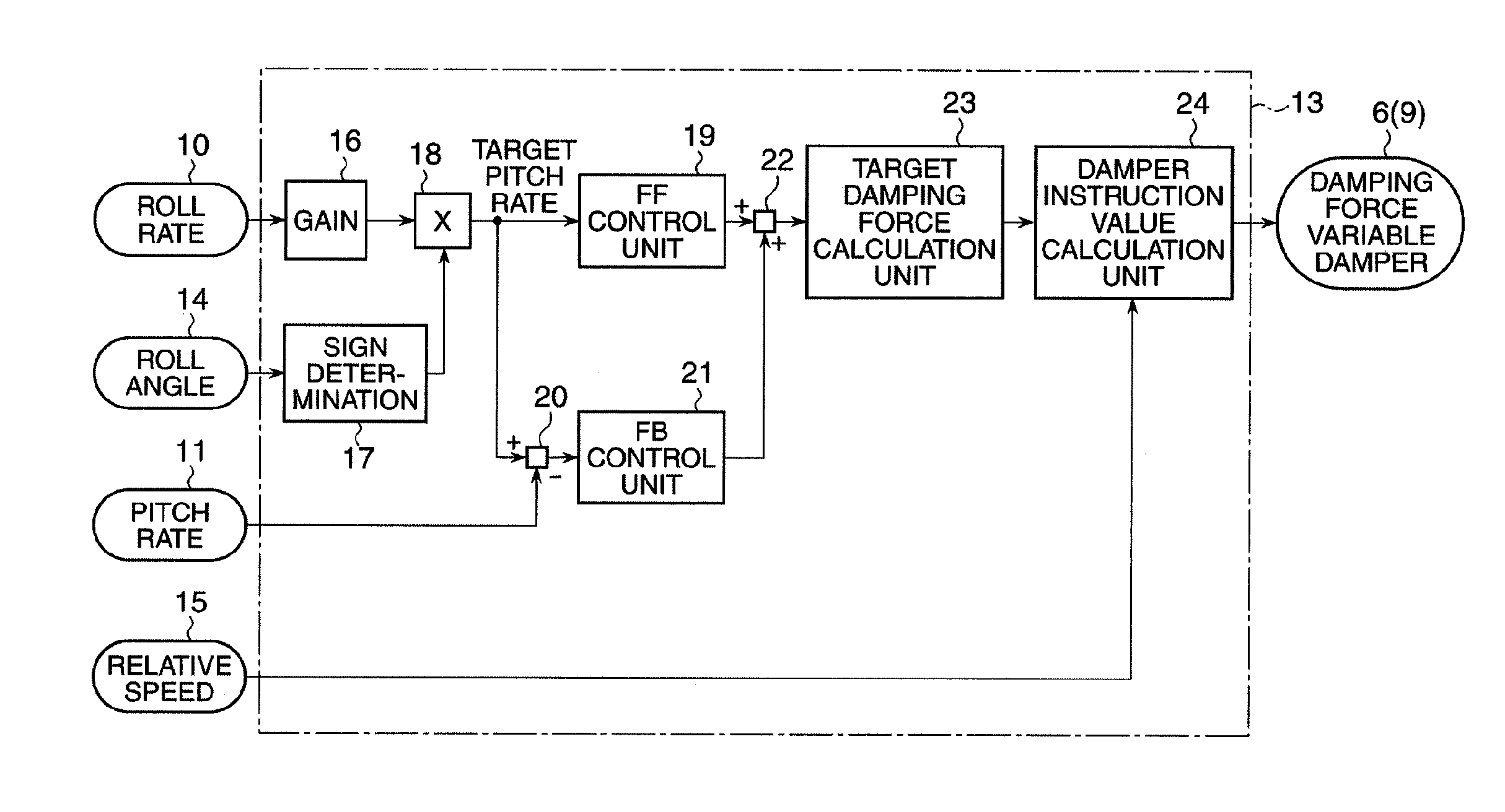
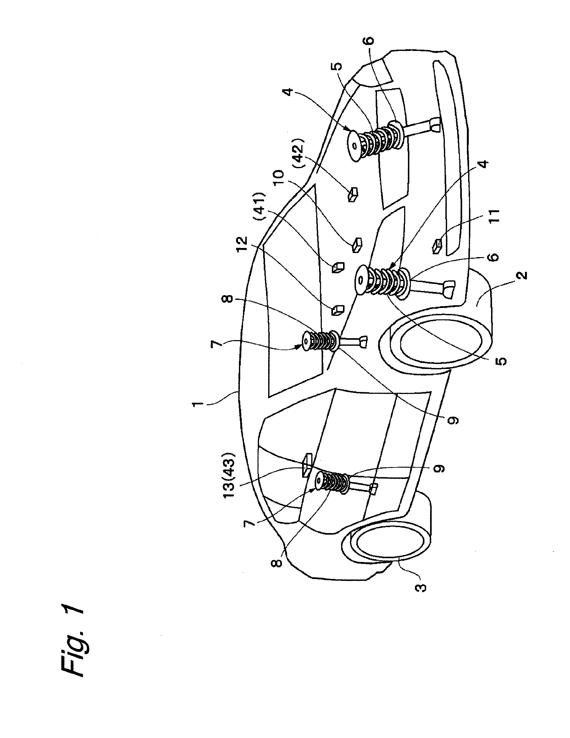
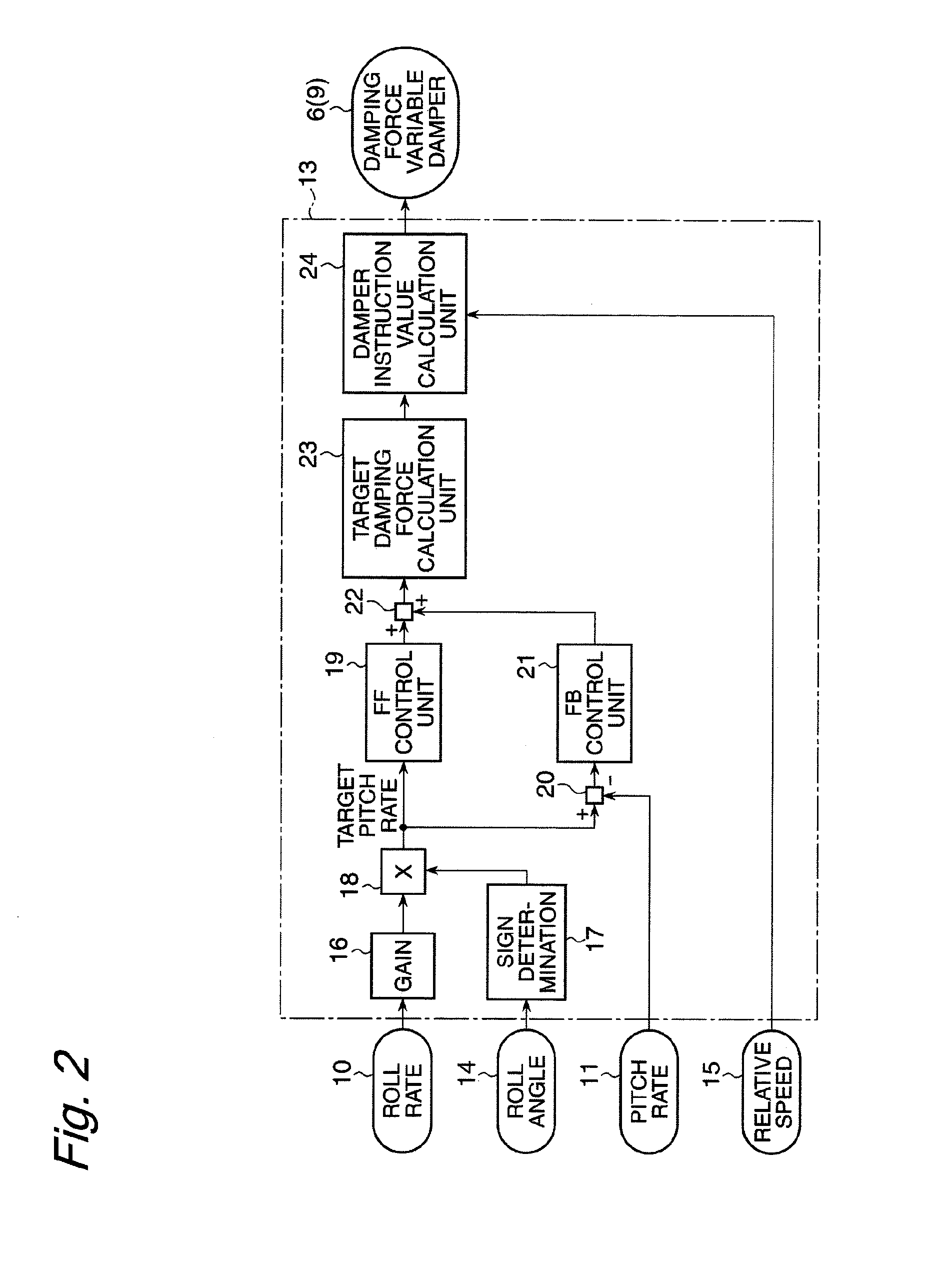
[0028]FIGS. 1 to 10 illustrate the present invention. In the drawings, reference numeral 1 denotes a vehicle body constituting a vehicle main structure. The vehicle body is provided with, for example, front left and right wheels 2 (only one of them shown) and rear left and right wheels 3 (only one of them shown) disposed at the lower side of the vehicle body.

[0029]Reference numeral 4 denotes front-wheel-side suspension apparatuses disposed between the front left and right wheels 2 and the vehicle body 1. The front-wheel-side suspension apparatuses 4 each include a left or right suspension spring 5 (hereinafter referred to as “spring 5”), and a left or right damping force adjustable shock absorber 6 (hereinafter referred to as “damping force variable damper 6”) disposed between the front left or right wheel 2 and the vehicle body 1 in parallel with the left or right spring 5. The damping force variable damper 6 constitutes a part of a pitch moment generation unit, which is a constitu...

second embodiment

[0060]Next, FIGS. 1 and 12 show the present invention. The second embodiment is characterized in that the second embodiment is configured to calculate a target pitch moment from a steering angle and a vehicle speed with use of a vehicle model, and control the attitude of the vehicle body without use of a roll rate sensor and a pitch rate sensor. Further, the second embodiment has been contrived in consideration of not only generation of pitching for stabilization of the rotational axis but also prevention of a roll behavior. In the following description of the second embodiment, like components are denoted by like reference numerals as those in the above-described first embodiment, and will not be repeatedly described.

[0061]In the drawings, reference numeral 41 denotes a steering angle sensor disposed at the vehicle body 1. The steering angle sensor 41 detects a steering angle (corresponding to a front wheel steering angle δf which will be described later) when a driver of the vehic...


PUM


Abstract

The present invention provides a vehicle body attitude control apparatus capable of improvement of cornering operability, steering stability, and a ride comfort while a vehicle is running. A controller includes a gain, a determination unit, a multiplication unit, an FF control unit, a difference calculation unit, an FB control unit, an average value calculation unit, a target damping force calculation unit, and a damper instruction value calculation unit so as to enable such control that a pitch rate and a roll rate are set into a proportional relationship while the vehicle is cornering. The controller calculates a target pitch rate proportional to the roll rate, variably controls a damping force characteristic of a damping force variable damper disposed at each of front left, front right, rear left, and rear right wheels so as to achieve the target pitch rate, and generates a pitch moment to be applied to the vehicle body accordingly.

Description

BACKGROUND OF THE INVENTION[0001]The present invention relates to a vehicle body attitude control apparatus for use in, preferably, a vehicle such as a four-wheeled automobile.[0002]Generally, there is known a vehicle body attitude control apparatus configured to reduce a roll rate by calculating lateral acceleration from a steering angle and a vehicle speed of the vehicle, obtaining lateral jerk by differentiating the lateral acceleration, and switching damping forces of the respective suspensions of the front, rear, left, and right wheels according to the lateral jerk (for example, refer to Japanese Patent Application Public Disclosure No. 2007-290650).[0003]Further, there is also known an apparatus capable of achieving a target behavior of a vehicle body to stabilize the attitude of the vehicle body by obtaining a target roll angle from lateral acceleration while the vehicle is running, calculating a target pitch angle according to the target roll angle, and performing feedback c...

Claims


Application Information

Patent Timeline
Patent Type & Authority Applications(United States)
IPC IPC(8): B60G17/016
CPCB60G17/08B60G2400/0511B60G2400/0521B60G2500/10B60G2400/204B60G2400/41B60G2400/0522B60G17/015B60W10/22B60W30/02B60W40/02B60W40/10B60W40/11
Inventor HIRAO, RYUSUKEYAMAKADO, MAKOTOICHIMARU, NOBUYUKI
Owner HITACHI ASTEMO LTD
Why Eureka
Try Eureka