
Thermal control system for fault detection and mitigation within a power generation system

a technology of power generation system and control system, which is applied in the direction of machines/engines, instruments, optical radiation measurement, etc., can solve the problems of premature wear of certain hrsg components, high cost and time-consuming of manually scanning the switchgear, and the fin separation from the conduit may reduce the efficiency of hrsg

Inactive Publication Date: 2012-02-09
GENERAL ELECTRIC CO
View PDF5 Cites 100 Cited by
  • Summary
  • Abstract
  • Description
  • Claims
  • Application Information

AI Technical Summary

Problems solved by technology

Unfortunately, separation of the fins from the conduits may decrease HRSG efficiency.
In addition, if a portion of the exhaust flow is warmer than desired, certain conduits may experience excessive steam pressure, thereby resulting in premature wear of certain HRSG components.
Unfortunately, the process of manually scanning the switchgear is expensive and time-consuming, thereby increasing the operational costs of the power generation system.
Consequently, the power transfer efficiency of the isolated phase bus may be substantially reduced, thereby decreasing the efficiency of the power generation system.

Method used


Image

  • Thermal control system for fault detection and mitigation within a power generation system
  • Thermal control system for fault detection and mitigation within a power generation system
  • Thermal control system for fault detection and mitigation within a power generation system

Examples


Embodiment Construction

[0016]One or more specific embodiments of the present invention will be described below. In an effort to provide a concise description of these embodiments, all features of an actual implementation may not be described in the specification. It should be appreciated that in the development of any such actual implementation, as in any engineering or design project, numerous implementation-specific decisions must be made to achieve the developers' specific goals, such as compliance with system-related and business-related constraints, which may vary from one implementation to another. Moreover, it should be appreciated that such a development effort might be complex and time consuming, but would nevertheless be a routine undertaking of design, fabrication, and manufacture for those of ordinary skill having the benefit of this disclosure.

[0017]When introducing elements of various embodiments of the present invention, the articles “a,”“an,”“the,” and “said” are intended to mean that ther...


PUM


Abstract

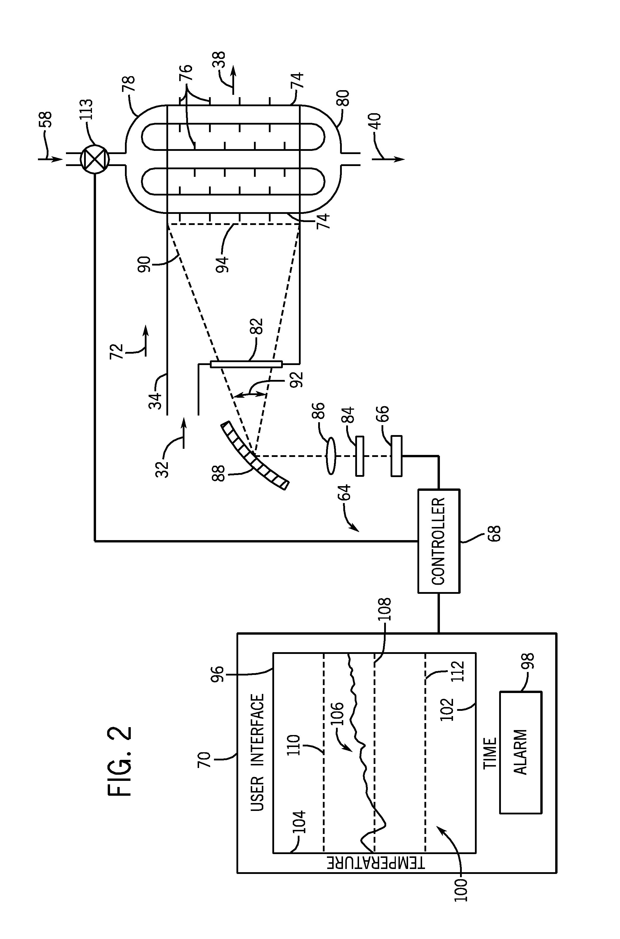
A system includes a radiation sensor configured to direct a field of view toward at least one conduit along a fluid flow path into a heat exchanger. The radiation sensor is configured to output a signal indicative of a temperature of the at least one conduit. The system also includes a controller communicatively coupled to the radiation sensor. The controller is configured to determine the temperature based on the signal, to compare the temperature to a threshold range, and to adjust a fluid flow through the fluid flow path or the at least one conduit if the temperature deviates from the threshold range.

Description

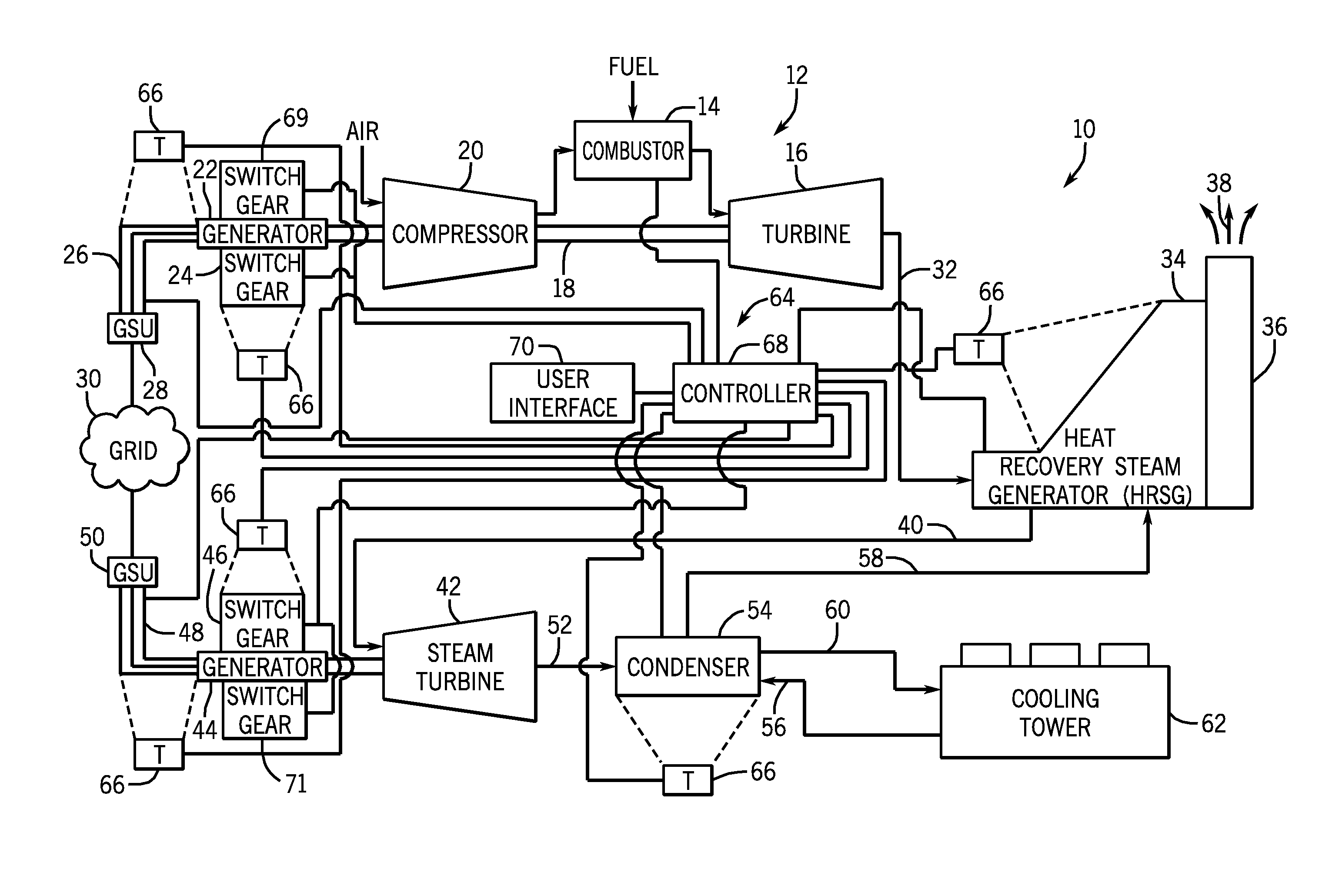
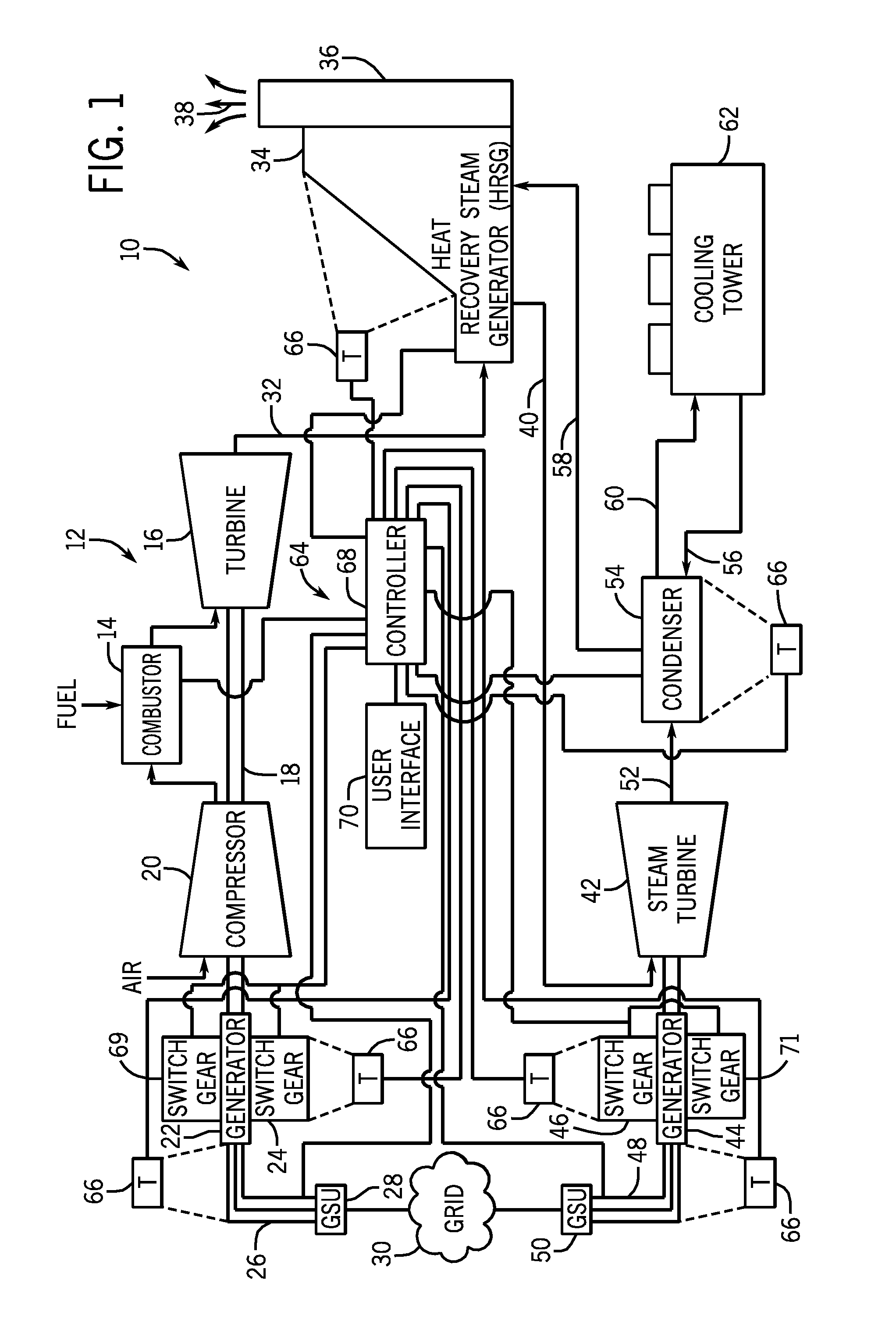
BACKGROUND OF THE INVENTION[0001]The disclosed subject matter relates to a thermal control system for fault detection and mitigation within a power generation system.[0002]Certain power generation systems include a gas turbine engine configured to combust a mixture of fuel and compressed air to produce hot combustion gases. The combustion gases may flow through a turbine to generate power for a load, such as an electric generator. To enhance efficiency, certain power generation systems employ a heat recovery steam generator (HRSG) to capture energy from the hot combustion gases exhausted from the turbine. In general, HRSGs convey a fluid, such as water, through multiple conduits in a direction crosswise (e.g., substantially perpendicular) to the flow of exhaust gas. As the exhaust gas flows across the conduits, heat is transferred from the exhaust gas to the water, thereby producing steam. The steam is then directed through a steam turbine to generate rotational motion, thereby driv...

Claims


Application Information

Patent Timeline
Patent Type & Authority Applications(United States)
IPC IPC(8): B60H1/00H02H5/04
CPCF01D17/085F01D21/003F02C6/18F02C9/28G01J5/0088Y02E20/16G01J5/0896G01J5/0014G01J5/0066F05D2270/303
Inventor CHILLAR, RAHUL JAIKARANMESTRONI, JULIO E.KAUFFMAN, ERIC J.ANSARI, ADIL
Owner GENERAL ELECTRIC CO
Learn More