Capacitive touch member, manufacturing method therefor, and capacitive touch detection apparatus

a capacitive touch and manufacturing method technology, applied in the direction of electronic switching, pulse technique, instruments, etc., can solve the problems of difficult to judge the degree of approach of a pen touch, the current practical use of the capacitive system, and the inability of other than the capacitive system to adapt to the curved touch panel. achieve sufficient electrical conductivity, strong mechanical characteristics, and high electrical conductivity

Inactive Publication Date: 2012-02-09
SONY CORP
View PDF0 Cites 78 Cited by
  • Summary
  • Abstract
  • Description
  • Claims
  • Application Information

AI Technical Summary

Benefits of technology

[0066]evaporating the washing solvent, and
[0070]The feature of the capacitive touch member and capacitive touch detection apparatus of the present invention resides in that a practical touch detection apparatus having a flexible shape or a stereoscopic shape has been achieved for the first time by using a light transmissive conductive layer containing a carbon nano linear structure as a detection electrode and combining the light transmissive conductive layer with a capacitive touch detection method.
[0071]The carbon nano linear structure has a diameter much smaller than a wavelength of visible light, and therefore causes visible light to pass therethrough well. In addition, some carbon nano linear structures have extremely high electrical conductivity like a metallic carbon nanotube, and show sufficient electrical conductivity at a small surface density. In addition, unlike an oxide-based transparent conductive material such as ITO, a carbon nanotube has supple and strong mechanical characteristics. Further, a carbon nanotube is chemically stable. As described above, a light transmissive conductive la

Problems solved by technology

A touch panel currently put into practical use is substantially limited to a flat panel having a flat touch surface.
There is described in Patent Document 1 that the touch panel has a resistive system, an electromagnetic induction system, an optical system, an ultrasonic system, and the like in addition to the capacitive system, but the systems other than the capacitive system are not suitable for the curved touch panel.
In addition, it is difficult to determine when to judge a touch based

Method used


Image

  • Capacitive touch member, manufacturing method therefor, and capacitive touch detection apparatus
  • Capacitive touch member, manufacturing method therefor, and capacitive touch detection apparatus
  • Capacitive touch member, manufacturing method therefor, and capacitive touch detection apparatus

Examples


embodiment 1

[0105]Hereinafter, a capacitive touch member, a capacitive touch detection apparatus, and a manufacturing method for the capacitive touch member according to Embodiment 1 of the present invention will be described. In this case, a carbon nanotube is used as the carbon nano linear structure.

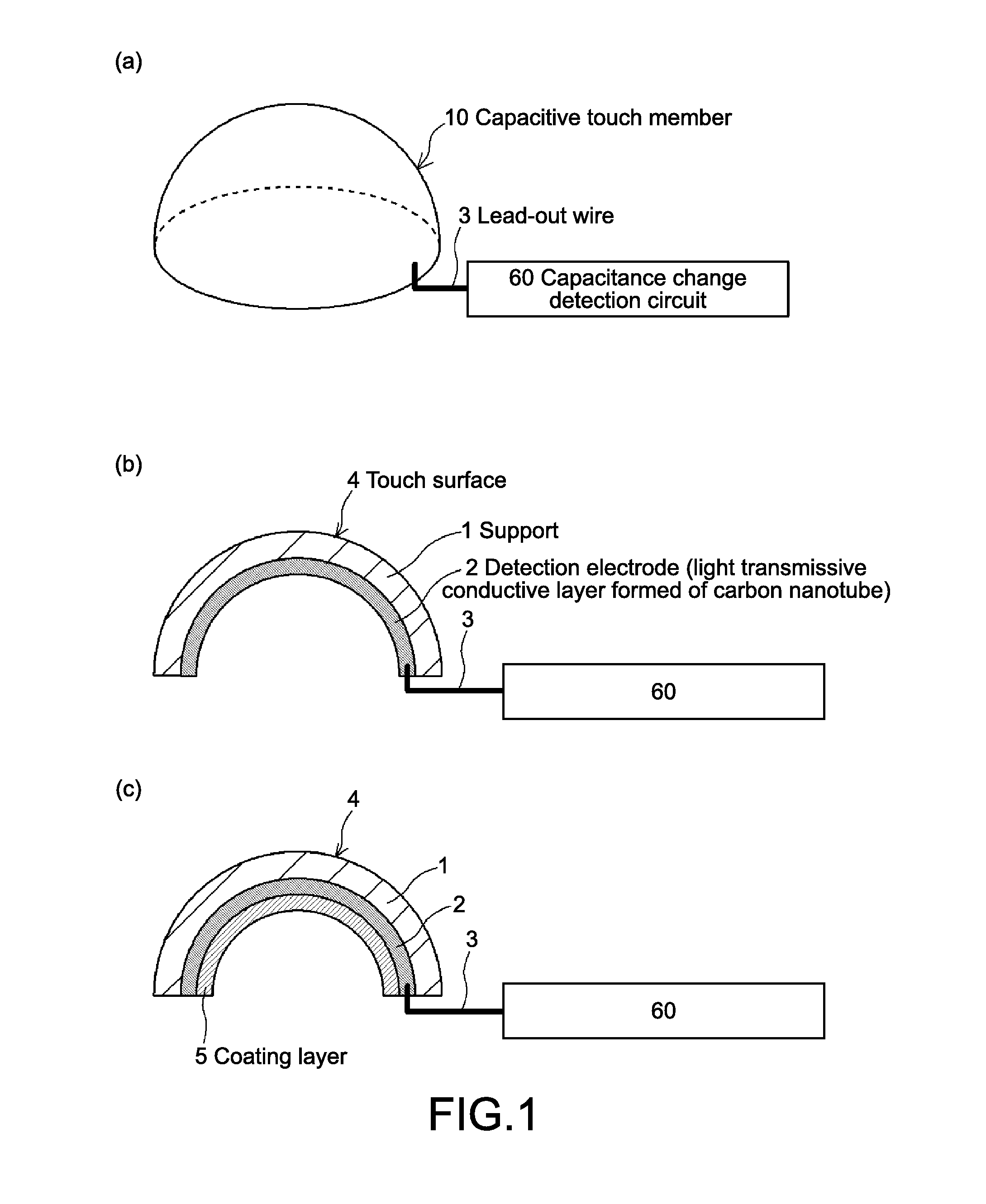
[0106]FIG. 1(a) is a perspective view showing a structure of a capacitive touch detection apparatus according to Embodiment 1, and FIG. 1(b) is a cross-sectional view thereof. The capacitive touch detection apparatus is constituted of a capacitive touch member 10 based on the first capacitive touch member of the present invention, and a capacitance change detection circuit 60.

[0107]The capacitive touch member 10 is constituted of a film-like or plate-like support 1 formed of an insulating material and having a stereoscopic shape, a detection electrode 2 that is formed of a light transmissive conductive layer containing a carbon nano linear structure and is arranged on at least a part of one surfac...

embodiment 2

[0136]Hereinafter, a capacitive touch member according to Embodiment 2 of the present invention will be described.

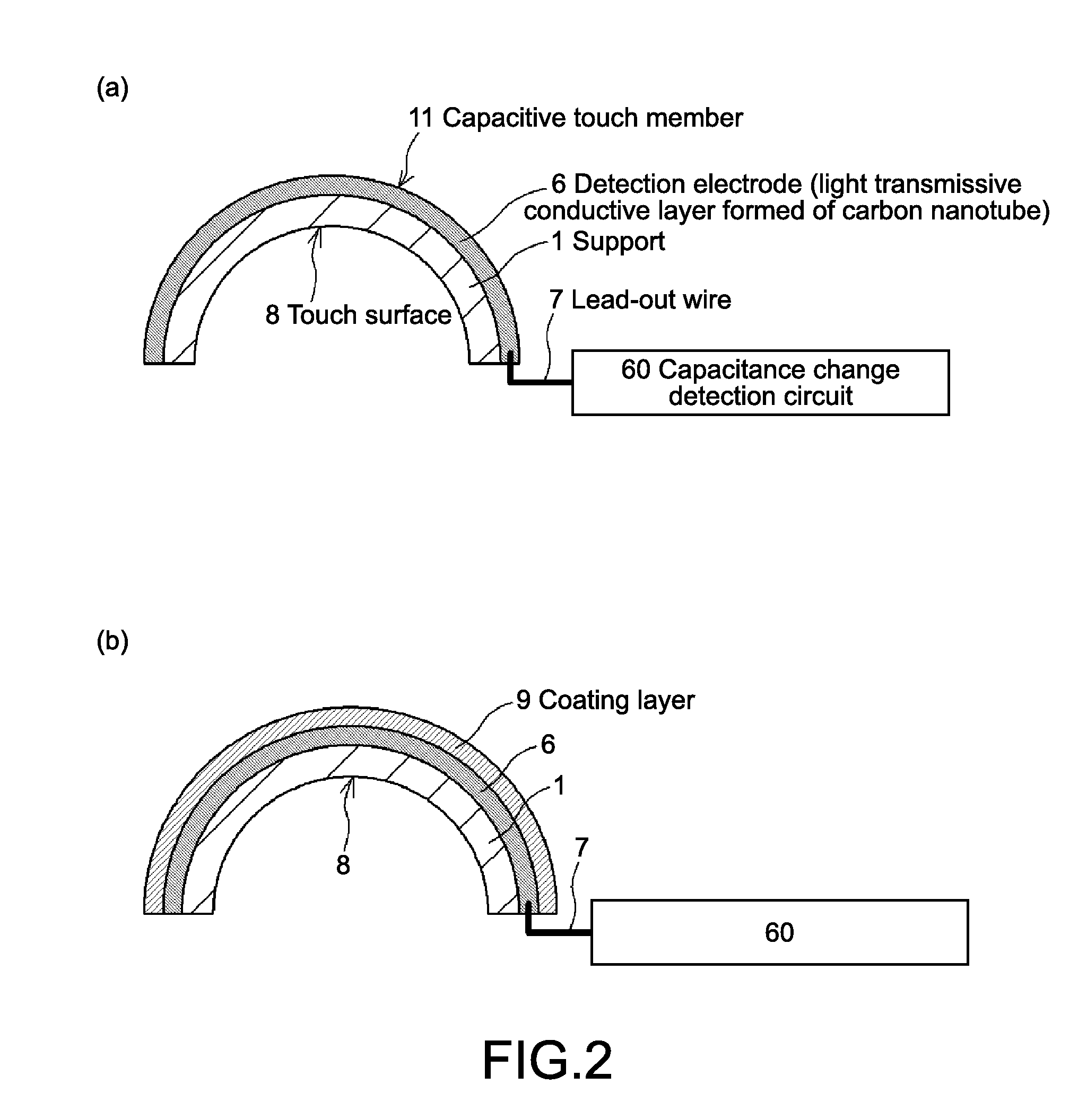
[0137]FIG. 5 are cross-sectional views each showing a structure of a capacitive touch detection apparatus according to Embodiment 2. The capacitive touch detection apparatus is constituted of a capacitive touch member 20 based on the second capacitive touch member of the present invention, and a capacitance change detection circuit 60.

[0138]In the capacitive touch member 20 shown in FIG. 5(a), a detection electrode 6 is arranged on the outer surface of a hemispherical support 1 (convex surface), and a protective film 22 that coats the detection electrode 6 is laminated thereon so that the surface of the protective film 22 is used as a touch surface 23. Further, a capacitive touch member 24 shown in FIG. 5(b), a detection electrode 2 is arranged on the inner surface of the hemispherical support 1 (concave surface), and a protective film 25 that coats the detection electro...

embodiment 3

[0141]Hereinafter, a capacitive touch member according to Embodiment 3 of the present invention will be described.

[0142]FIG. 6 is a cross-sectional view showing a structure of a capacitive touch detection apparatus according to Embodiment 3. The capacitive touch detection apparatus is constituted of a capacitive touch member 30 based on the third capacitive touch member of the present invention, and a capacitance change detection circuit 60.

[0143]In the capacitive touch member 30 shown in FIG. 6, a detection electrode 6 is arranged on the outer surface of a hemispherical support 1 (convex surface), and a protective film 22 that coats the detection electrode 6 is laminated thereon so that the surface of the protective film 22 is used as a touch surface 23. In addition, a detection electrode 2 is also arranged on the inner surface of the hemispherical support 1 (concave surface), and a protective film 25 that coats the detection electrode 2 is laminated thereon so that the surface of ...


PUM

PropertyMeasurementUnit
Flexibilityaaaaaaaaaa
Shapeaaaaaaaaaa
Electrical conductoraaaaaaaaaa

Abstract

[Object] To provide a capacitive touch member having a flexible shape or a stereoscopic shape and includes a light transmissive detection electrode, a manufacturing method therefor, and a capacitive touch detection apparatus including the capacitive touch member.
[Solving Means] Produced is a capacitive touch member (10) including a film-like or plate-like support (1) that is formed of an insulating material and has a flexible shape or a stereoscopic shape, a detection electrode (2) that is arranged on at least a part of one surface of the support (1) and formed of a light transmissive conductive layer containing a carbon nano linear structure such as a carbon nanotube, and a lead-out wire (3) that is led out from the detection electrode (2). A capacitive touch detection apparatus is constituted of the touch member (10) and a capacitance detection circuit (60) that is electrically connected to the detection electrode (2) via the lead-out wire (3) and detects a change in capacitance due to approach or contact of a human body with respect to a touch surface (4). The detection electrode (2) may be coated with a protective film, and a surface of the protective film may be used as a touch surface.

Description

TECHNICAL FIELD[0001]The present invention relates to a capacitive touch member having a flexible shape or a stereoscopic shape, a manufacturing method therefor, and a capacitive touch detection apparatus including the capacitive touch member.BACKGROUND ART[0002]As input apparatuses for electronic equipment, touch panels are used in various fields. The touch panel is constituted of a touch member having a touch surface approached or contacted by a contact object such as a part of a human body, e.g., a finger or a pen tip, a control circuit unit that generates an electrical signal corresponding to a touch position on the touch surface that is designated by the approach or contact, and the like. In many cases, the touch panel is configured such that the touch member is arranged in front of an image display apparatus and a user determines a touch position based on a display image transmitted through a touch surface. In this case, the touch member needs to be light transmissive such tha...

Claims


Application Information

Patent Timeline
IPC IPC(8): G06F3/044H05K3/00
CPCG06F3/044H03K17/962Y10T29/49124H03K2017/9604H03K2217/960755H03K2017/9602
Inventor ENOKI, OSAMU
Owner SONY CORP
Why Eureka
Try Eureka