Method of varying the flow rate of fluid from a medical pump and hybrid sensor system performing the same

a technology of hybrid sensor and flow rate, which is applied in the direction of volume flow testing/calibration, process and machine control, instruments, etc., can solve the problems of high cost of ultrasonic sensors, inability to monitor multiple sensors, and inability to integrate hybrid sensor systems to achieve three sensing functions in one system

Active Publication Date: 2012-02-09
ICU MEDICAL INC
View PDF3 Cites 61 Cited by
  • Summary
  • Abstract
  • Description
  • Claims
  • Application Information

AI Technical Summary

Benefits of technology

[0016]A system and method of varying the flow rate of fluid from a medical pump through tubing is disclosed. The system and method also provides for detection of air bubbles in the fluid within the tubing. The system includes a capacitive micromachined ultrasonic transducer sensor assembly adapted to operatively couple with the tubing to transmit and receive acoustic signals directed at or through the tubing. A processor or controller in communication with the sensor assembly determines tubing dimensions, fluid flow velocity of fluid in the tubing, fluid flow rate of fluid in the tubing, and phases of fluid in the tubing based upon the acoustic signals received from the sensor assembly. The processor or controller can determine the in...

Problems solved by technology

There exists no highly integrated hybrid sensor system capable of implementing three sensing functions in a single system.
While non-invasive flow meters that use ultrasonic sensors or lasers exist along with non-invasive thickness gauges that use ultrasonic sensor capability along with separate sensors that can detect air bubbles and fluid within tubing, no sensors exist that can monitor multiple characteristics of tubing and fluid within the tubing in order to alter the flow rate of fluid from the pump through the tubing.
However, ultrasonic sensors are high cost and have impedance matching problems and thus this basic electric piezoelectric technology needs to be replaced or enhanced.
Specifically, there are two impedance matching problems that exist with current piezoelectric ultrasonic transducers.
First, there is a problem with acoustic impedance matching.
The second problem associated with piezoelectric transducers is electric impedance matching.
Specifically, piezoelectric material, due to its material property of havin...

Method used


Image

  • Method of varying the flow rate of fluid from a medical pump and hybrid sensor system performing the same
  • Method of varying the flow rate of fluid from a medical pump and hybrid sensor system performing the same
  • Method of varying the flow rate of fluid from a medical pump and hybrid sensor system performing the same

Examples


Embodiment Construction

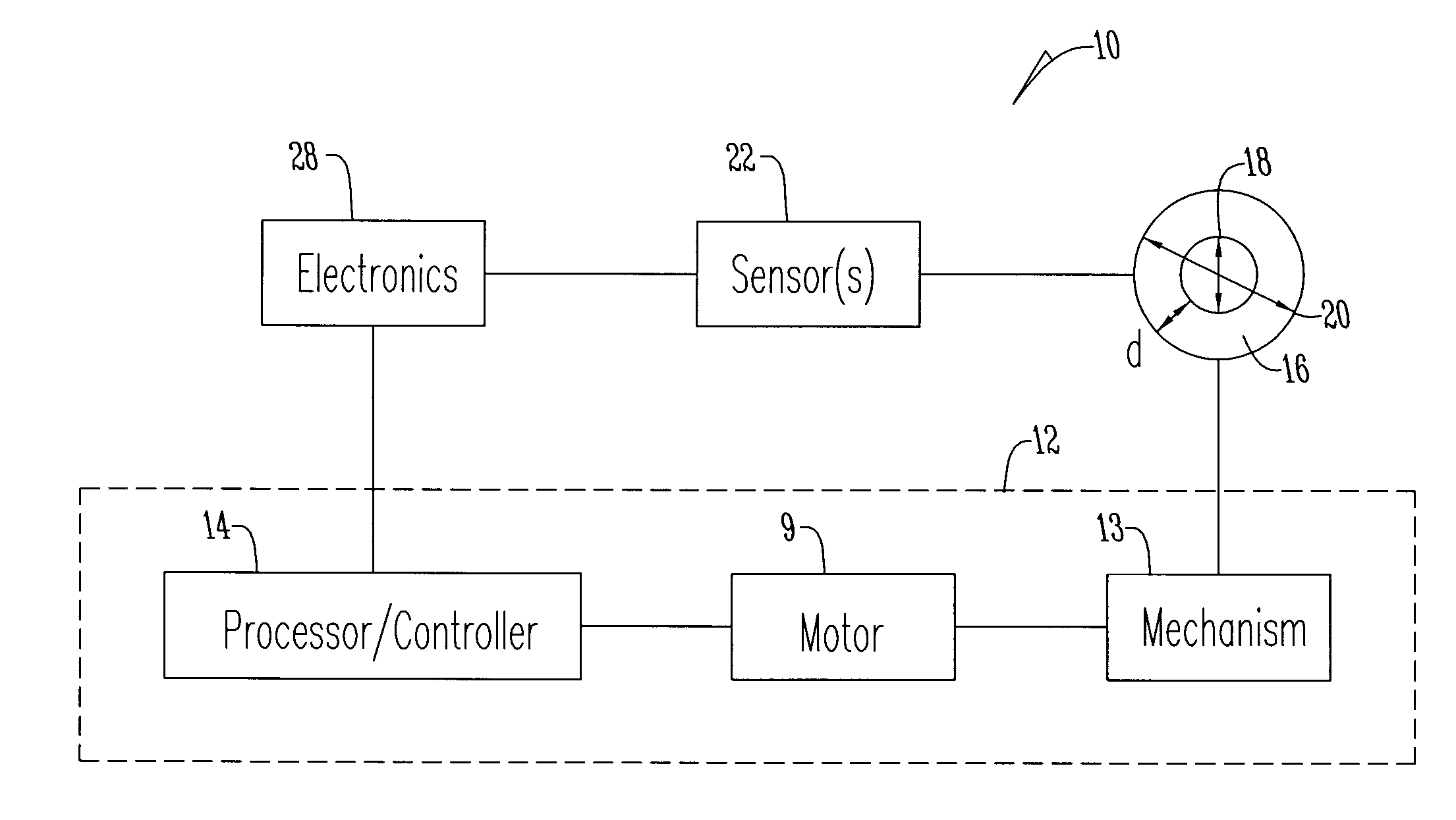
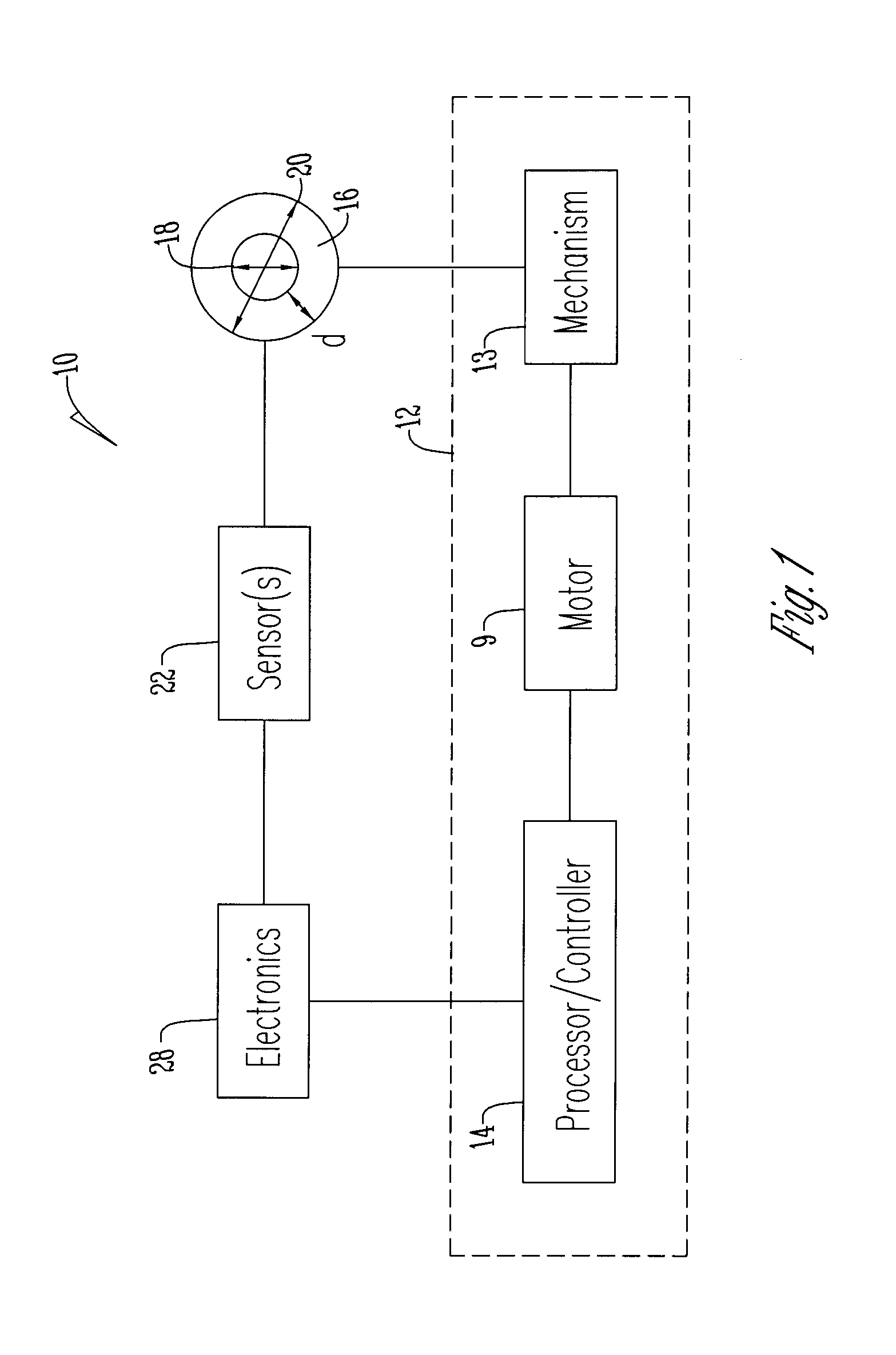
[0028]The figures show a fluid flow rate compensation system or monitoring system 10. As best seen in FIG. 1, the system 10 utilizes a pump system 12 that in one embodiment is a peristaltic pump. The pump 12 includes a controller 14 or processor that contains an algorithm to adjust fluid flow by operating a motor 9 that manipulates or operatively engages via a pumping mechanism 13 a section of tubing 16 through which fluid flows. The tubing 16 can be of any shape, including the standard circular or alternatively hexagonal, square or the like. The tubing 16 has an inner diameter 18, an outer diameter 20, and in addition has a predetermined ovality, modulus elasticity and other such inherent characteristics. The tubing 16 may be any type of material including PVC, a polymer composite, a conductive polymer composite (CPC) or the like.

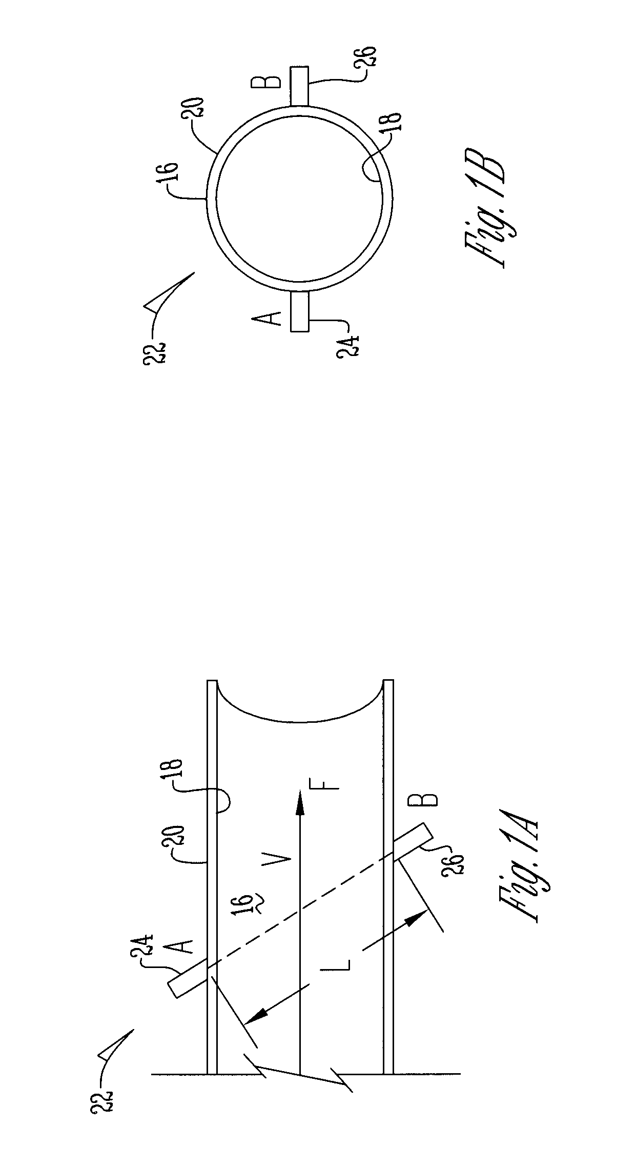
[0029]A sensing system 22 is detachably secured to the tubing 16. The sensing system 22 includes first and second capacitive micromachined ultrasonic tran...


PUM


Abstract

A system and method of varying the flow rate of fluid from a medical pump through tubing includes determining an inner diameter of the tubing and fluid flow velocity of fluid in the tubing with a controller based on acoustic signals received by a capacitive micromachined ultrasonic transducer sensor system and then determining and adjusting a fluid flow rate of fluid in the tubing with the controller. In addition, the same sensor system also detects air bubbles in the fluid in the tubing.

Description

CROSS REFERENCE TO RELATED APPLICATION[0001]This application claims the benefit of U.S. Provisional Application No. 61 / 370,962 filed Aug. 5, 2010.BACKGROUND OF THE INVENTION[0002]This invention relates to pumps for delivering fluids to a patient. More specifically, the invention relates to a system and method of varying the flow rate of fluid to a patient through a tube based on monitored characteristics of the tubing and fluid within the tubing.[0003]There exists no highly integrated hybrid sensor system capable of implementing three sensing functions in a single system. While non-invasive flow meters that use ultrasonic sensors or lasers exist along with non-invasive thickness gauges that use ultrasonic sensor capability along with separate sensors that can detect air bubbles and fluid within tubing, no sensors exist that can monitor multiple characteristics of tubing and fluid within the tubing in order to alter the flow rate of fluid from the pump through the tubing.[0004]Ultras...

Claims


Application Information

Patent Timeline
IPC IPC(8): A61M5/168
CPCA61M5/16877A61M5/16886A61M5/172A61M5/365A61M2205/3375A61M2205/50A61M2205/502G01F25/0007G01F1/662G01F1/74G01F25/10
Inventor JOHNSON, THOMAS D.FATHALLAH, MARWAN A.BAEK, KYUSUK
Owner ICU MEDICAL INC
Why Eureka
Try Eureka