Low delay and area efficient soft error correction in arbitration logic

a soft error correction and low delay technology, applied in error correction/detection using convolutional codes, instruments, coding, etc., can solve the problems of soft error becoming more significant, storage element values can flip, and soft error may occur more frequently in recent vlsi circuits

Inactive Publication Date: 2012-02-09
IBM CORP
View PDF6 Cites 14 Cited by
  • Summary
  • Abstract
  • Description
  • Claims
  • Application Information

AI Technical Summary

Problems solved by technology

However, these storage elements can flip their values due to soft errors.
Soft error refers to an error on data stored in a computing system that does not damage hardware of the computing system but corrupts the data.
Because of a trend of high-density and low-power consumption in semiconductor designing / manufacturing technology (e.g., 20-nm CMOS technology), a soft error may occur more frequently in recent VLSI circuits.
Therefore, a soft error becomes more significant problem as the digital circuits are designed based on nanotechnology (e.g., 30-nm CMOS technology).
For example, if the two copies have different values, there exists a soft error on the data.
Although this duplication method is simple and easy to implement, it increases the number of storage elements in the digital circuits unacceptably in terms of hardware size and power consumption.
However, a naïve ECC method is not efficient for the arbitration logic device.
However, this increase becomes not acceptable both in hardware size and in power consumption as digital circuits become dense and operate in a low-power environment (e.g., Vdd=1.6V).
Furthermore, an ECC correction delay (i.e., the time that an ECC correction logic device takes to fix a soft error) is added to the critical path in the arbitration logic device, thus increasing latency for the arbitration.
Thus, they are lack of generality because these proposed methods rely on semiconductor device technologies (e.g., 40 nm CMOS technology) and synthesis tools (e.g., synthesis tools from Cadence®, etc.) through which these method are implemented on semiconductor devices.
Sometimes, they are difficult or even impossible to be implemented.
However, depending on a design of a digital circuit, it may not be easy to add such mechanism in the digital circuit.

Method used


Image

  • Low delay and area efficient soft error correction in arbitration logic
  • Low delay and area efficient soft error correction in arbitration logic
  • Low delay and area efficient soft error correction in arbitration logic

Examples


Embodiment Construction

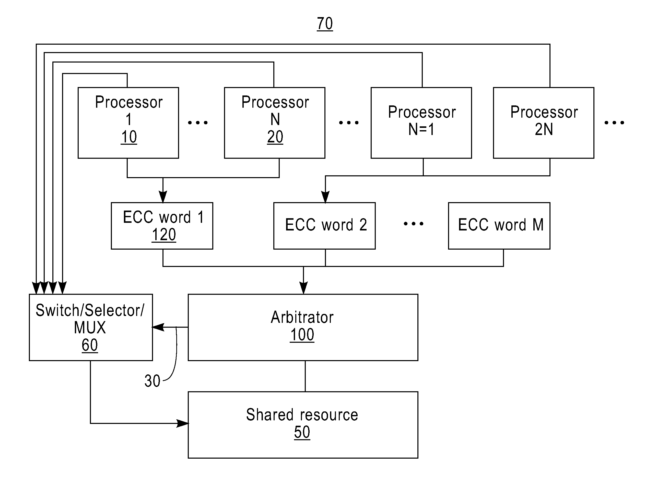
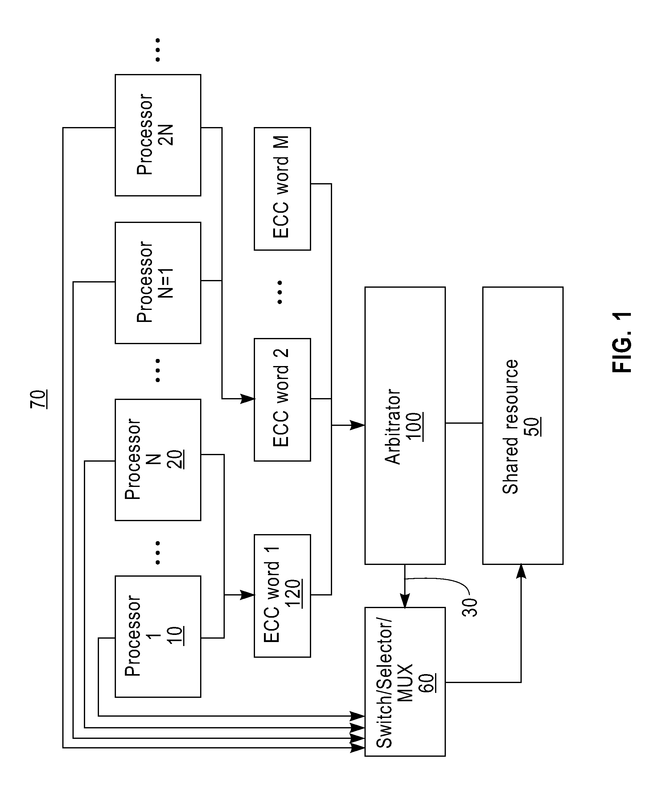
[0021]In one embodiment, FIG. 1 illustrates a computing environment 70 where an arbitration logic device can be employed in one embodiment. This computing environment 70 includes, but is not limited to: a plurality of processors (e.g., processor 1 (10), processor N (20), etc.), a switching device 60, a shared resource 50 (e.g., a shared memory device, a shared bus, etc.). To access the shared resource 50, a requestor (e.g., a processor, etc.) which wants to access the shared resource issues an (access) request including requestor status information to the arbitration logic device 100. In one embodiment, multiple requests are combined into an ECC word. In other words, “N” piece of requestor status information is combined to form an ECC word. For example, an ECC word 1 (120) includes, but is not limited to: status information of processor 1 (10), status information of processor 2 (not shown), status information of processor 3 (not shown), status information of processor N (20), and EC...


PUM


Abstract

There is provided an arbitration logic device for controlling an access to a shared resource. The arbitration logic device comprises at least one storage element, a winner selection logic device, and an error detection logic device. The storage element stores a plurality of requestors' information. The winner selection logic device selects a winner requestor among the requestors based on the requestors' information received from a plurality of requestors. The winner selection logic device selects the winner requestor without checking whether there is the soft error in the winner requestor's information.

Description

CROSS-REFERENCE TO RELATED APPLICATIONS[0001]The present invention is related to the following commonly-owned, co-pending United States patent applications, the entire contents and disclosure of each of which is expressly incorporated by reference herein as if fully set forth herein. Attorney docket No. (YOR920090171US1 (24255)), for “USING DMA FOR COPYING PERFORMANCE COUNTER DATA TO MEMORY”; Attorney docket No. (YOR920090169US1 (24259)) for “HARDWARE SUPPORT FOR COLLECTING PERFORMANCE COUNTERS DIRECTLY TO MEMORY”; Attorney docket No. (YOR920090168US1 (24260)) for “HARDWARE ENABLED PERFORMANCE COUNTERS WITH SUPPORT FOR OPERATING SYSTEM CONTEXT SWITCHING”; Attorney docket No. (YOR920090473US1 (24595)), for “HARDWARE SUPPORT FOR SOFTWARE CONTROLLED FAST RECONFIGURATION OF PERFORMANCE COUNTERS”; Attorney docket No. (YOR920090474US1 (24596)), for “HARDWARE SUPPORT FOR SOFTWARE CONTROLLED FAST MULTIPLEXING OF PERFORMANCE COUNTERS”; Attorney docket No. (YOR920090533US1 (24682)), for “COND...

Claims


Application Information

Patent Timeline
Patent Type & Authority Applications(United States)
IPC IPC(8): G06F11/08H03M13/00
CPCG06F11/10H03M13/136H03M13/1505H03M13/1515H03M13/152H03M13/19H03M13/23
Inventor SUGAWARA, YUTAKA
Owner IBM CORP
Why Eureka
Try Eureka