Steel piston with cooling gallery and method of construction thereof

a technology of steel pistons and cooling galleries, which is applied in the direction of pistons, combustion engines, machines/engines, etc., can solve the problems of limiting overall engine size, and the degree of compression height, so as to reduce the compression height and weight of the piston, increase the compression load, and increase the strength and durability

Active Publication Date: 2012-02-16
TENNECO INC
View PDF23 Cites 60 Cited by
  • Summary
  • Abstract
  • Description
  • Claims
  • Application Information

AI Technical Summary

Benefits of technology

[0007]A piston constructed in accordance with this invention is constructed of steel, thereby providing the piston with enhanced strength and durability to withstand increased compression loads within a cylinder bore, such as those seen in modern high performance engines. Further, due to the novel configuration of the piston, the compression height (CH) and weight of the piston are able to be minimized, thereby allowing an engine in which the pistons are deployed to be made more compact and lightweight.

Problems solved by technology

However, while desirable to increase compression loads within the combustion chamber, it remains necessary to maintain the piston within workable limits.
As such, although desirable to increase compression loads within the combustion chamber, there is a tradeoff in that these “increases” limit the degree of which the compression height, and thus, overall engine size, can be decreased.
Further, the degree to which the engine weight can be reduced is compromised in that the increase of mechanical and thermal loads imposed on the piston require that they be made of steel.

Method used


Image

  • Steel piston with cooling gallery and method of construction thereof
  • Steel piston with cooling gallery and method of construction thereof
  • Steel piston with cooling gallery and method of construction thereof

Examples


Embodiment Construction

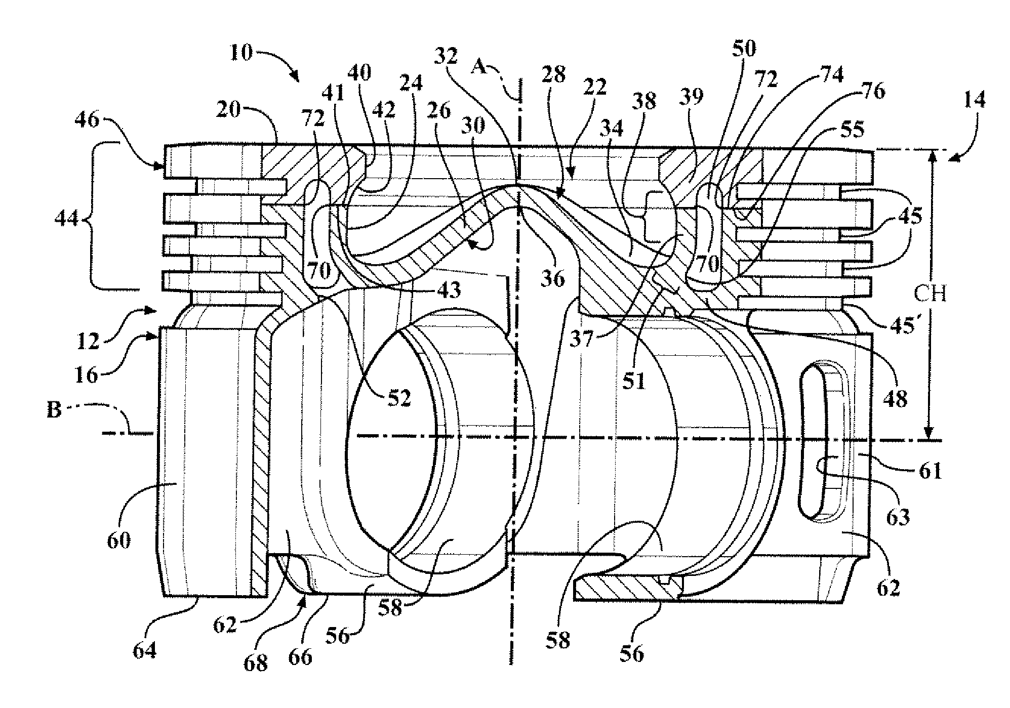
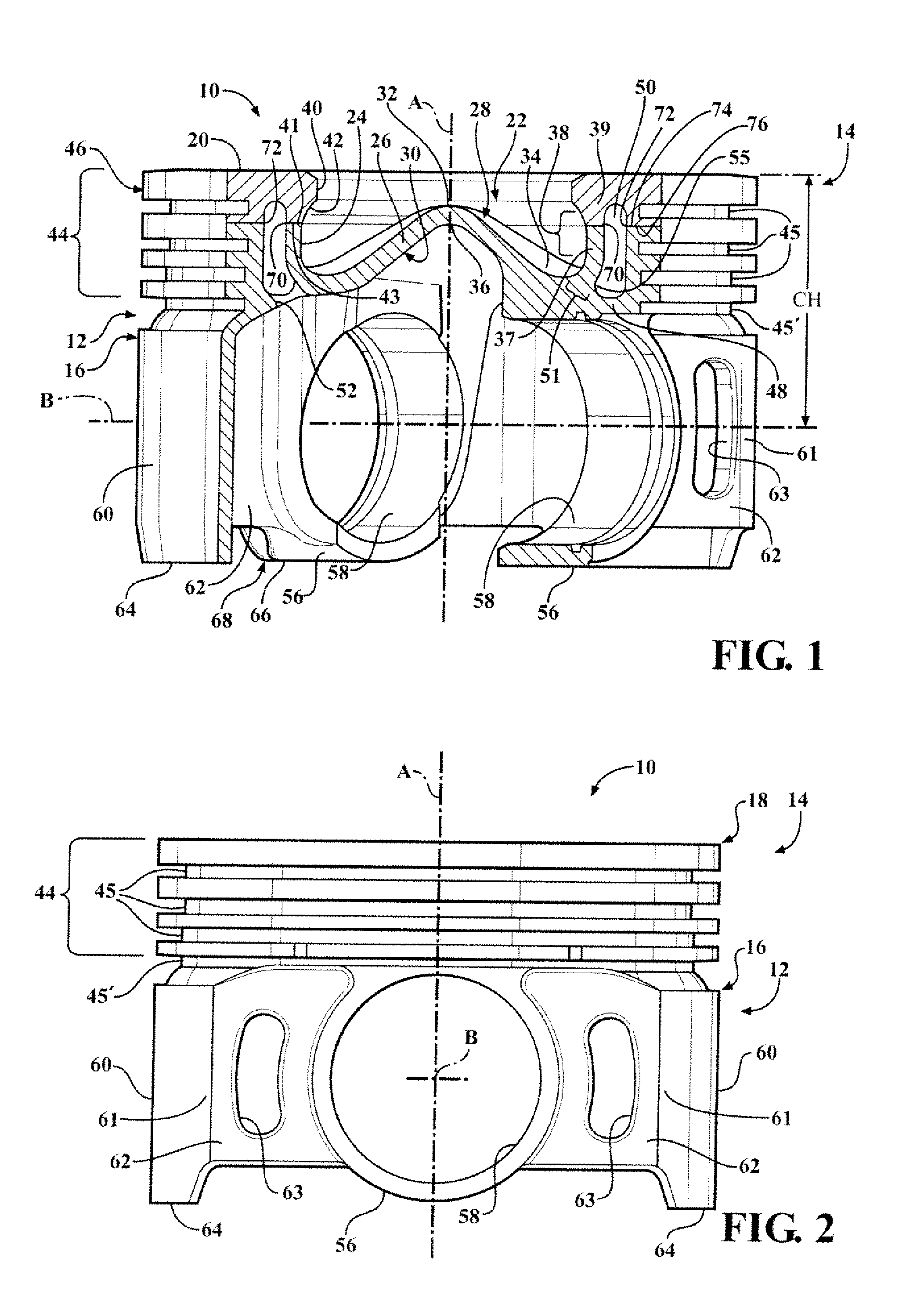
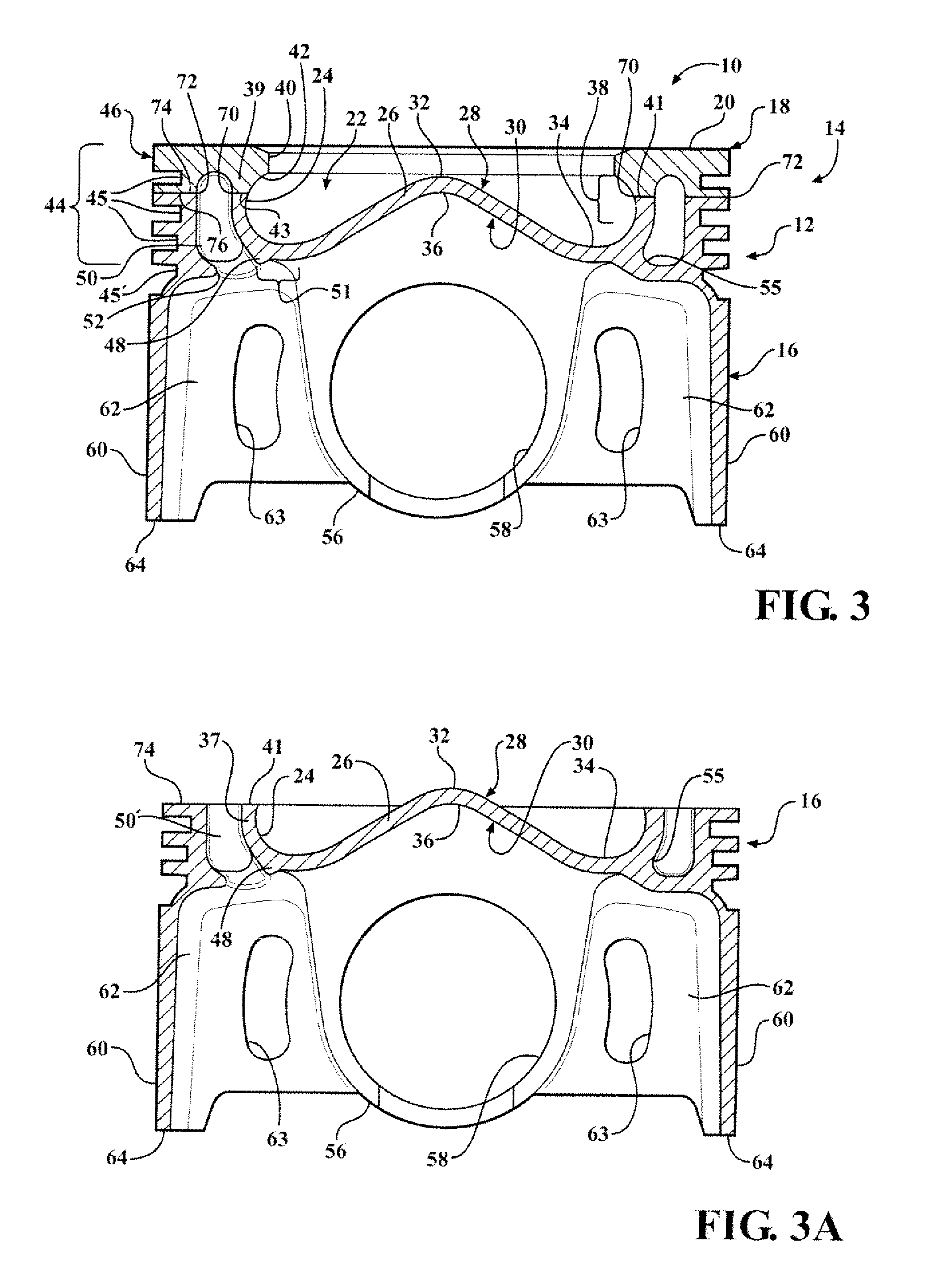
[0034]Referring in more detail to the drawings, FIG. 1 illustrates a partially sectioned perspective view of a piston 10 constructed in accordance with one presently preferred embodiment of the invention for reciprocating movement in a cylinder bore or chamber (not shown) of an internal combustion engine, such as a modern, compact, high performance vehicle engine, for example. The piston 10 has a body 12 made of at least two separate pieces that are initially fabricated as separate parts and subsequently joined to one another within a head region 14 across some form in of a weld joint (i.e., induction weld, friction weld, braze joint, charge carrier rays, laser, resistance, and the like). The two parts comprise a bottom part 16, and a top part 18. Reference to “top”, “bottom”, “upper” and “lower” herein are relative to the piston being oriented along a vertical longitudinal central piston axis A along which the piston 10 reciprocates in use. This is for convenience and is not to be ...


PUM


Abstract

A piston and method of construction is provided. The piston includes a top part fixed to a bottom part. The top part has an uppermost surface with annular inner and outer upper joining surfaces depending therefrom. The bottom part has a pair of pin bosses with pin bores aligned with one another along a pin bore axis; a pair of upwardly extending annular inner and outer lower joining surfaces and a combustion bowl wall. Inner and outer weld joints fix the inner and outer upper and lower joining surfaces to one another. An annular cooling gallery is formed laterally between the upper and lower joining surfaces. The inner weld joint joining the top part to the bottom part is located within the combustion bowl wall and configured to minimized the compression height of the piston.

Description

CROSS-REFERENCE TO RELATED APPLICATIONS[0001]This application is a Continuation-in-Part and claims the benefit of U.S. application Ser. No. 12 / 896,202, filed Oct. 1, 2010 and U.S. Provisional Application Ser. No. 61 / 258,956, filed Nov. 6, 2009, which is incorporated herein by reference in its entirety.BACKGROUND OF THE INVENTION[0002]1. Technical Field[0003]This invention relates generally to internal combustion engines, and more particularly to pistons and their method of construction.[0004]2. Related Art[0005]Engine manufacturers are encountering increasing demands to improve engine efficiencies and performance, including, but not limited to, improving fuel economy, reducing oil consumption, improving fuel systems, increasing compression loads within the cylinder bores, reducing heat lost through the piston, reducing friction losses, decreasing engine weight and making engines more compact. In order to achieve these goals, the piston size and their compression height need to be re...

Claims


Application Information

Patent Timeline
Patent Type & Authority Applications(United States)
IPC IPC(8): F02F3/00F02F3/26
CPCF02F3/003F02F3/22Y02T10/125F02B23/0672F02F2003/0061Y02T10/12F02F3/00
Inventor MUSCAS, FLORIN
Owner TENNECO INC
Why Eureka
Try Eureka