Power supply system and fixed and movable body therefor

a power supply system and movable body technology, applied in the direction of process and machine control, cable arrangement between relatively moving parts, instruments, etc., can solve the problems of system heavyness, noise, and inability to supply power to a movable body such as a robot that needs to freely move on the floor surface, so as to reduce psychological anxiety, reduce the impedance of a load section, reduce the effect of affecting the stability of the power supply

Active Publication Date: 2012-02-16
EXH CORP
View PDF1 Cites 26 Cited by
  • Summary
  • Abstract
  • Description
  • Claims
  • Application Information

AI Technical Summary

Benefits of technology

[0028]The power supply system of claim 1, the movable body of claim 8 or the fixed body of claim 9 makes it possible to supply power without bringing the power-transmitting electrodes into contact with the power-receiving electrodes, and therefore eliminates the need for exposing the power-transmitting electrodes to the power-consuming region, whereby the power supply system, the movable body or the fixed body can eliminate the danger of giving an electrical shock to a human body when the human body touches a power-transmitting electrode, and can relieve the psychological anxiety. For this reason, installation thereof in a place to have people inside, such as an office space, is facilitated. Particularly, the first capacitor and first coil connected to each other in parallel between the first power-receiving electrode and second power-receiving electrode are provided to the movable body, and power is supplied to the load under the condition that causes parallel resonance between the first capacitor and first coil. Therefore, the impedance of a load section, which includes the first capacitor, the first coil and the load, can be increased. As a result, the first coupling capacitor and second coupling capacitor are less likely to have a voltage drop, and stable power supply is made possible regardless of changes in capacitances of the first coupling capacitor and second coupling capacitor.
[0029]Further, in the power supply system of claim 2, the second capacitor and second coil connected to each other in parallel between the first power-transmitting electrode and second power-transmitting electrode are provided to the fixed body, whereby it is made possible to reduce the amount of reactive current to be output from the AC power supply. This enables the AC power supply to be more compact.
[0030]Further, in the power supply system of claim 3, the third capacitor and third coil connected to each other in parallel are provided to the movable body, in such a manner as to be laid parallel to the first and second power-transmitting electrodes and to the second capacitor and second coil, whereby...

Problems solved by technology

In order to obtain higher power transmission efficiency, however, the conventional contactless power supply system as described above requires a lot of positional restrictions including the need for closely positioning an induction line and a coil, and the need for aligning these induction line and coil with each other so that a magnetic flux generated by electrical conduction through the induction line may pass through the central axis of the coil.
Therefore, there has been a problem that, since power supply has been possible only on a fixed route such as a guideway, power supply to a movable body such as a robot that needs to freely move on a floor surface has been impossible.
Further, a magnetic body such as an iron core should be used in forming a magnetic path, which raises another ...

Method used


Image

  • Power supply system and fixed and movable body therefor
  • Power supply system and fixed and movable body therefor
  • Power supply system and fixed and movable body therefor

Examples


embodiment 1

Effects of Embodiment 1

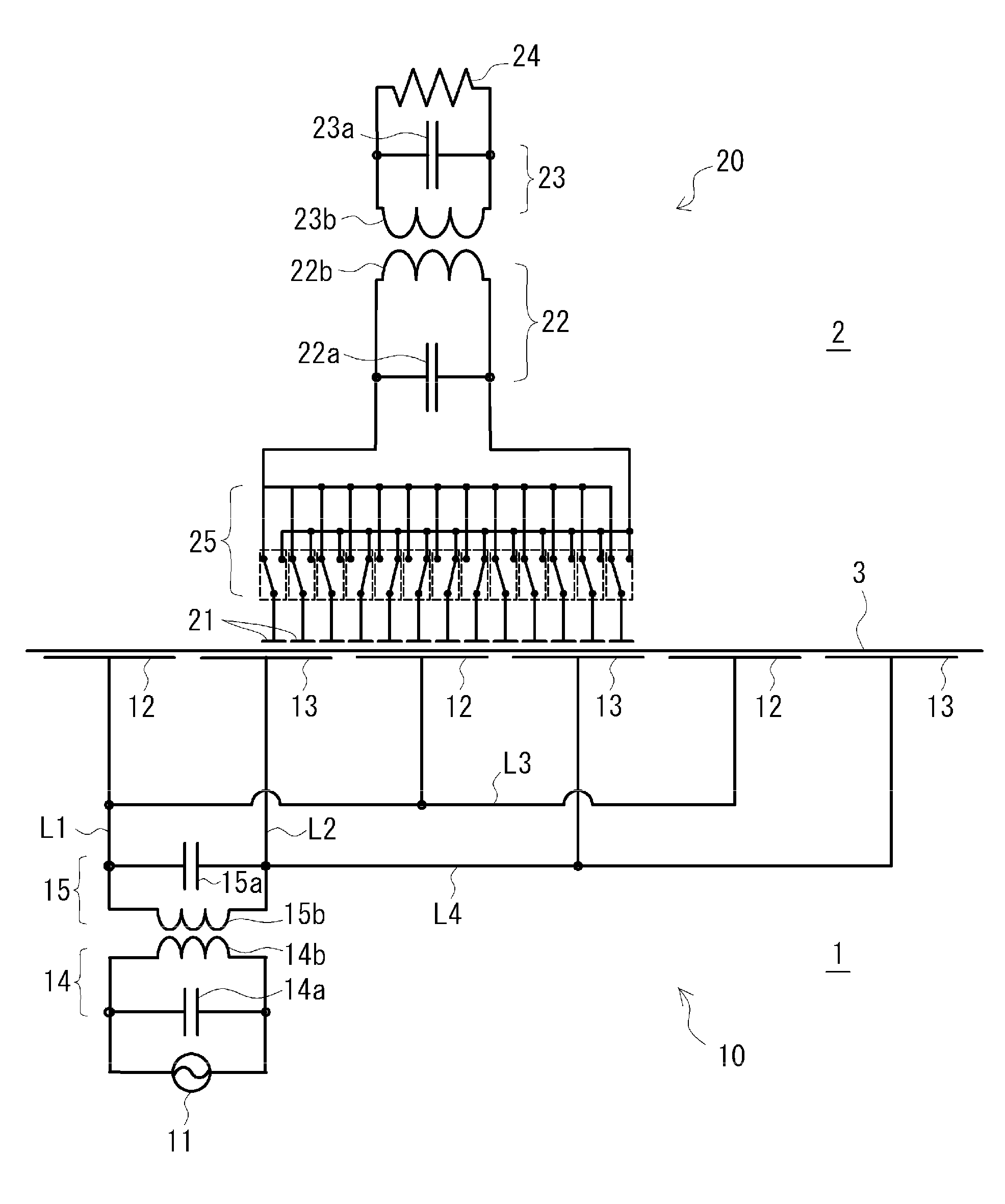
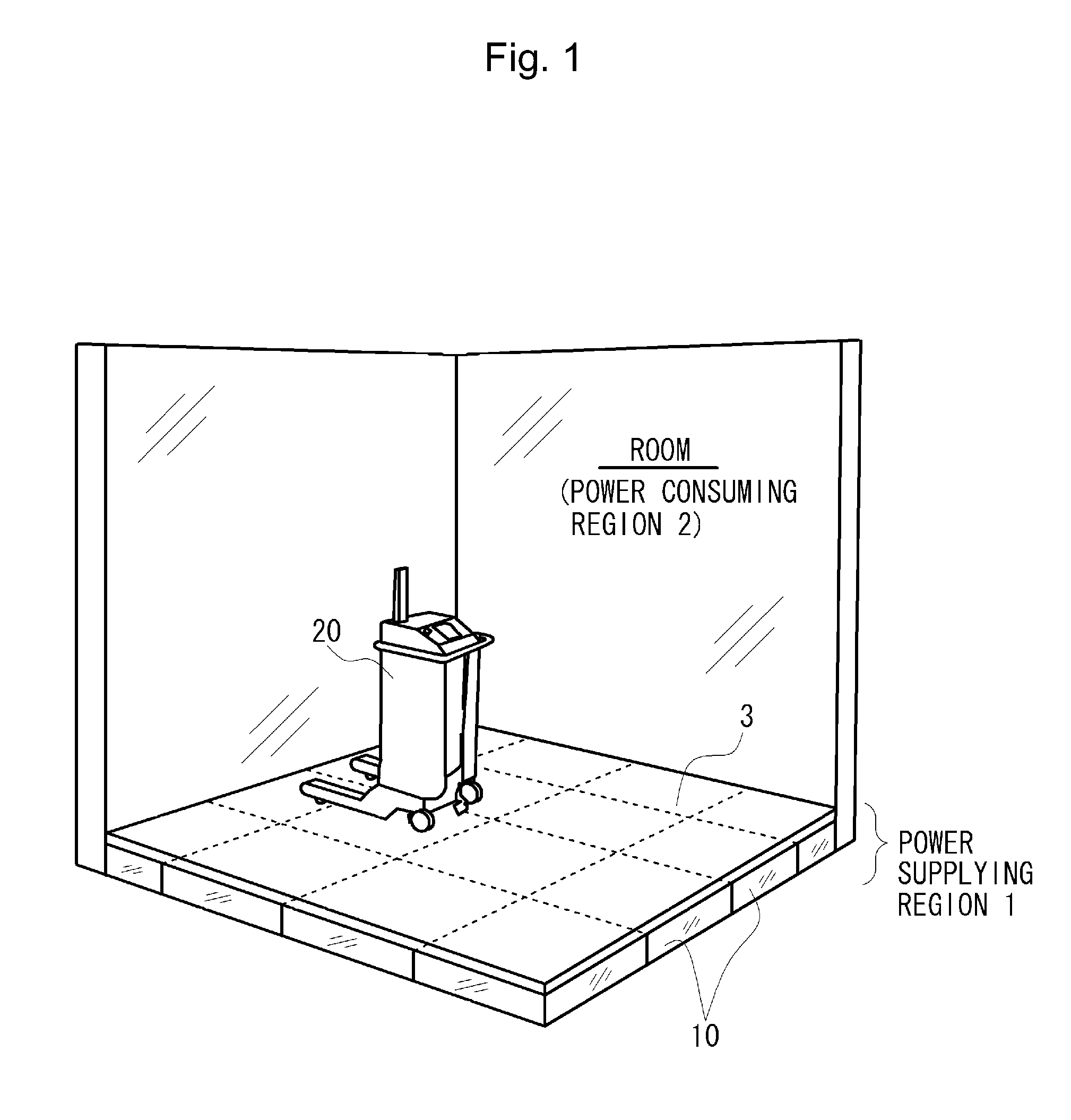
[0084]As described above, the power-transmitting electrodes 12 and 13 are not exposed to the power-consuming region 2 according to Embodiment 1, which makes it possible to eliminate the danger of electric shock occurring when a human body touches the power-transmitting electrodes 12 or 13, and also makes it possible to relieve the psychological anxiety. Therefore, installation of the power supply system in a place to have people inside, such as an office space, is facilitated.

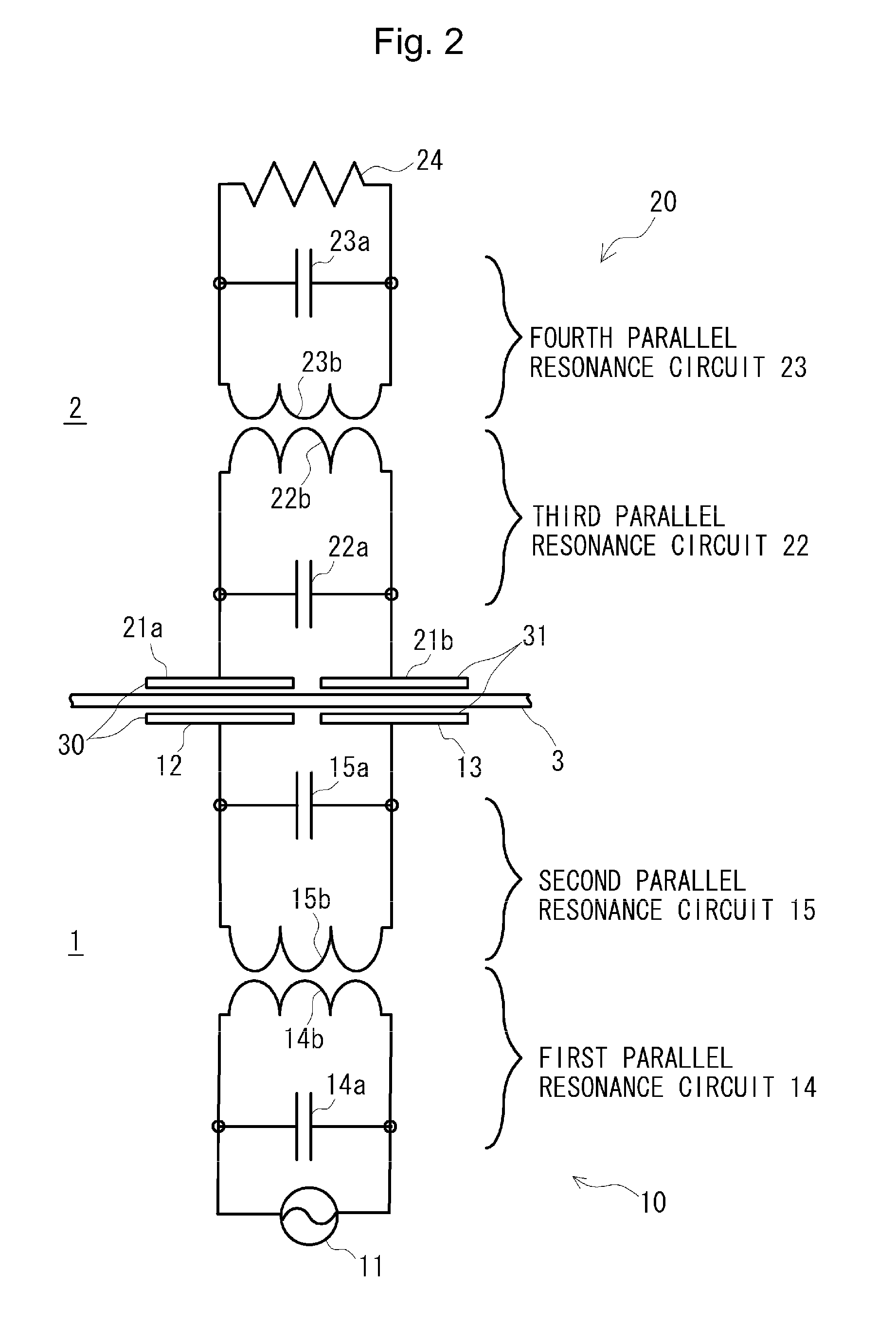
[0085]Particularly, the third parallel resonance circuit 22 or fourth parallel resonance circuit 23 is provided to the movable body 20, and power is transmitted to the load 24 under the conditions that cause these parallel resonance in the parallel resonance circuits. This makes it possible to increase the impedance of the load section 50 which includes the parallel resonance circuit and the load 24. This enables reduction of voltage drops in the coupling capacitors 30 and 31, and enables...

embodiment 2

Effects of Embodiment 2

[0110]According to Embodiment 2, the plural power-transmitting electrodes 12 and 13 are provided side by side, and the connection state of each of the power-receiving electrodes 21 to the load 24 is automatically changed by use of the determination / switching section 25 on the basis of which of the power-transmitting electrodes 12 or 13 opposed to the power-receiving electrode 21. Therefore, power supply to the movable body 20 is enabled regardless of whatever arbitrary position the movable body 20 is placed with respect to the fixed body 10.

Embodiment 3

[0111]Next, Embodiment 3 will be described. This embodiment is an embodiment not only having the configuration of Embodiment 2 but also including the second capacitor and second coil provided to each set of the first power-transmitting electrode and second power-transmitting electrode. In this embodiment, conditions that cause parallel resonance in the respective sets of the second capacitors and the third coils...

embodiment 3

Effects of Embodiment 3

[0128]According to Embodiment 3, the first parallel resonance circuits 14 are provided to the respective sets of the plural power-transmitting electrodes 12 and 13. This enables reduction of the amount of reactive current to be output from the AC power supply 11, and therefore enables the AC power supply 11 to be more compact.

[0129]The different first parallel resonance circuits 14 of each set of the plural power-transmitting electrodes 12 and 13 are configured to have parallel resonance frequencies of different values. This makes it possible to, only by changing the output frequency of the AC power supply 11, cause resonance only in an arbitrary one of the first parallel resonance circuits14 and supply power only to the power-transmitting electrodes 12 and 13 which have this first parallel resonance circuits 14. This makes it unnecessary that any circuit, such as a switch, for switching between the sets of the power-transmitting electrodes 12 and 13 for suppl...


PUM


Abstract

Provided is a power supply system which makes it possible to stably supply power regardless of changes in placement of electrodes. The power supply system for supplying power to a load (24). The fixed body (10) includes: a first power-transmitting electrode (12) and second power-transmitting electrode (13); and an AC power supply (11) to supply AC power to the first power-transmitting electrode (12) and second power-transmitting electrode (13). The movable body (20) includes: a first power-receiving electrode (21a) and second power-receiving electrode (21b) to form a first coupling capacitor (30) and a second coupling capacitor (31), respectively, by being placed in a manner opposed to and not contacting corresponding ones of the first power-transmitting electrode (12) and second power-transmitting electrode (13) while facing one side of an interface, the one side not being faced by these power-transmitting electrodes, and a first capacitor (22a) and first coil (22b) connected to one another in parallel between the first power-receiving electrode (21a) and second power-receiving electrode (21b). The AC power supply (11) transmits power to the load (24) via the first and second coupling capacitors under a condition that causes parallel resonance between the first capacitor (22a) and first coil (22b).

Description

TECHNICAL FIELD[0001]The present invention relates to a power supply system for supplying electric power to various loads, and also relates to a movable body and fixed body therefor.[0002]This application is based upon Japanese Patent Application No. 2009-038329, filed in Japan on Feb. 20, 2009, the content of which is incorporated herein by reference.BACKGROUND ART[0003]In general, a power supply system, which supplies power to various loads placed on a floor surface, is either of the followings in a broad sense: a contact-type power supply system configured to supply power by bringing electrodes, which are provided in a manner exposed over the floor surface, into direct contact with electrodes provided on the bottom surface of a load; and a contactless power supply system configured to supply power without bringing electrodes, which are provided in an unexposed state underneath a floor surface, into direct contact with electrodes of a load.[0004]Patent Document 1, for example, dis...

Claims


Application Information

Patent Timeline
IPC IPC(8): H02J3/00H02G11/00
CPCH02J5/005H01F38/14H02J7/025H02J50/80H02J50/05H02J50/402H02J50/12
Inventor HARAKAWA, KENICHIOSHI, YUUJI
Owner EXH CORP
Why Eureka
Try Eureka