Apparatus And Method For Rotating-Sensorless Identification Of Equivalent Circuit Parameters Of An AC Synchronous Motor

Active Publication Date: 2012-02-16
BAUMULLER NURNBERG GMBH
View PDF11 Cites 9 Cited by
  • Summary
  • Abstract
  • Description
  • Claims
  • Application Information

AI Technical Summary

Benefits of technology

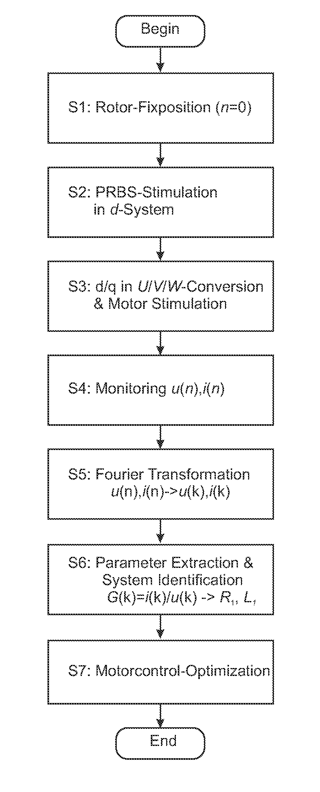
[0035]According to an advantageous further development of the identification apparatus the parameter identification unit can comprise a Fourier transformation means, in particular an FFT/DFT means for the Fourier transformation of discontinuous d/q scanning signal values according to the Welch method and comprise a parameter determination means, in particular a Levenberg-Marquardt transmission function-parameter determination means. Accordingly, the parameter identification unit comprises a Fourier transformation means for transferring the supplied and measured voltage- and current time scan values U1d, I1d and comprises a parameter determination means that, starting from the transmission function G1 present in the frequency range, can carry out a determination of the transmission function coefficients b0 and b1 and from this of the system parameters. The calculating processes necessary for this can be performed, for example, in a DSP, a microcontroller of an FPGA, in a PC or a small computer, whereby a logical and structural separation between test signal generation, measured value storage, Fourier transformation and parameter determination is possible. The signal processing and the subsequent numeric process can advantageously be provided as software implementation at least partially on a motor regulator or motor control apparatus.
[0036]Thus, it is conceivable to build the Fourier transformation means up as FPGA in order to realize a rapid Fourier transformation with the aid of a static switching circuit, and to implement the parameter identification means as variable calculating software on a high-performance DSP of a motor control regulator. A test signal production and measured value stora

Problems solved by technology

In the short-circuit test the motor must be secure

Method used


Image

  • Apparatus And Method For Rotating-Sensorless Identification Of Equivalent Circuit Parameters Of An AC Synchronous Motor
  • Apparatus And Method For Rotating-Sensorless Identification Of Equivalent Circuit Parameters Of An AC Synchronous Motor
  • Apparatus And Method For Rotating-Sensorless Identification Of Equivalent Circuit Parameters Of An AC Synchronous Motor

Examples


Embodiment Construction

[0053]In the figures the same or similar components are designated with the same reference numbers.

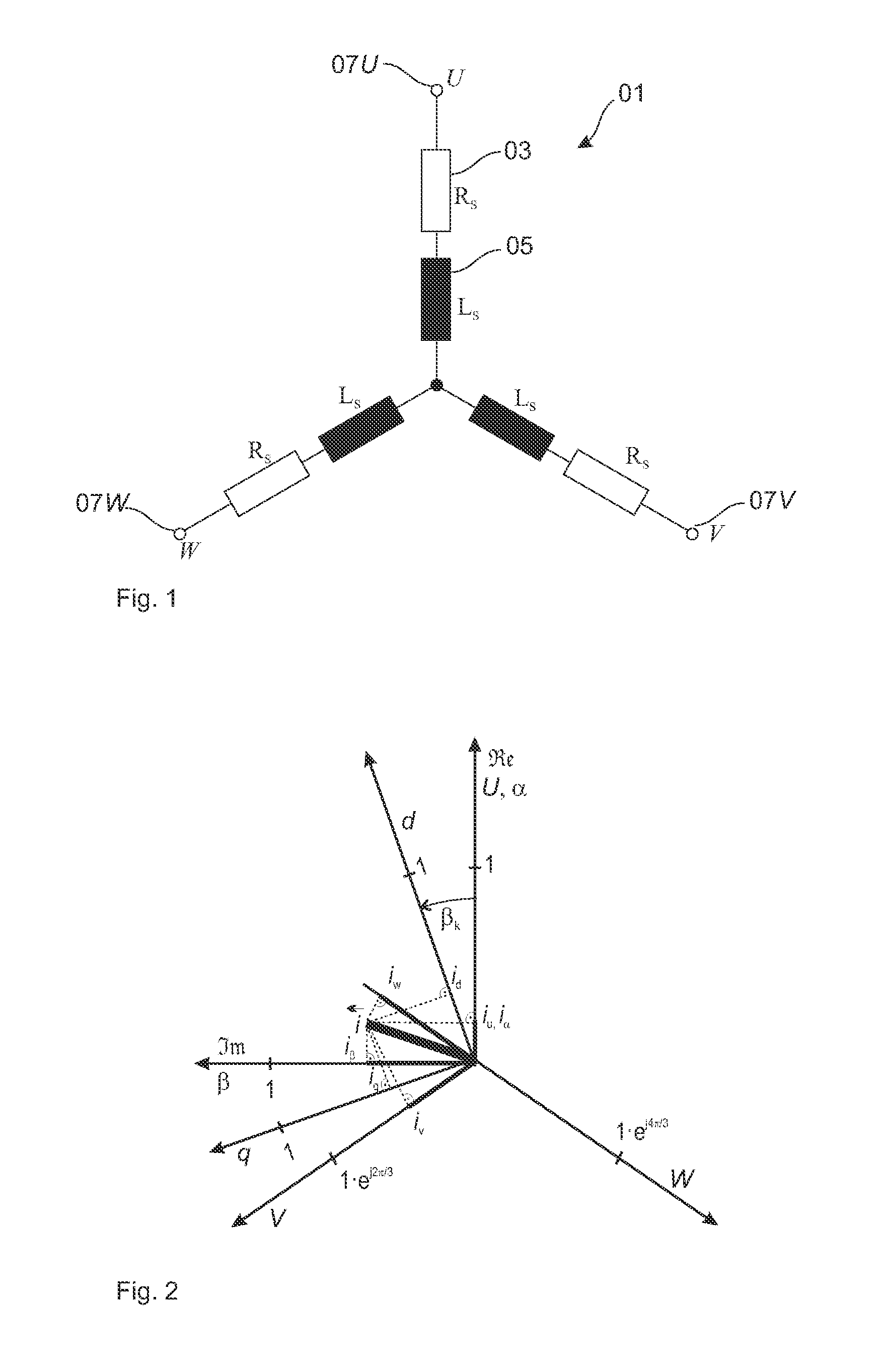
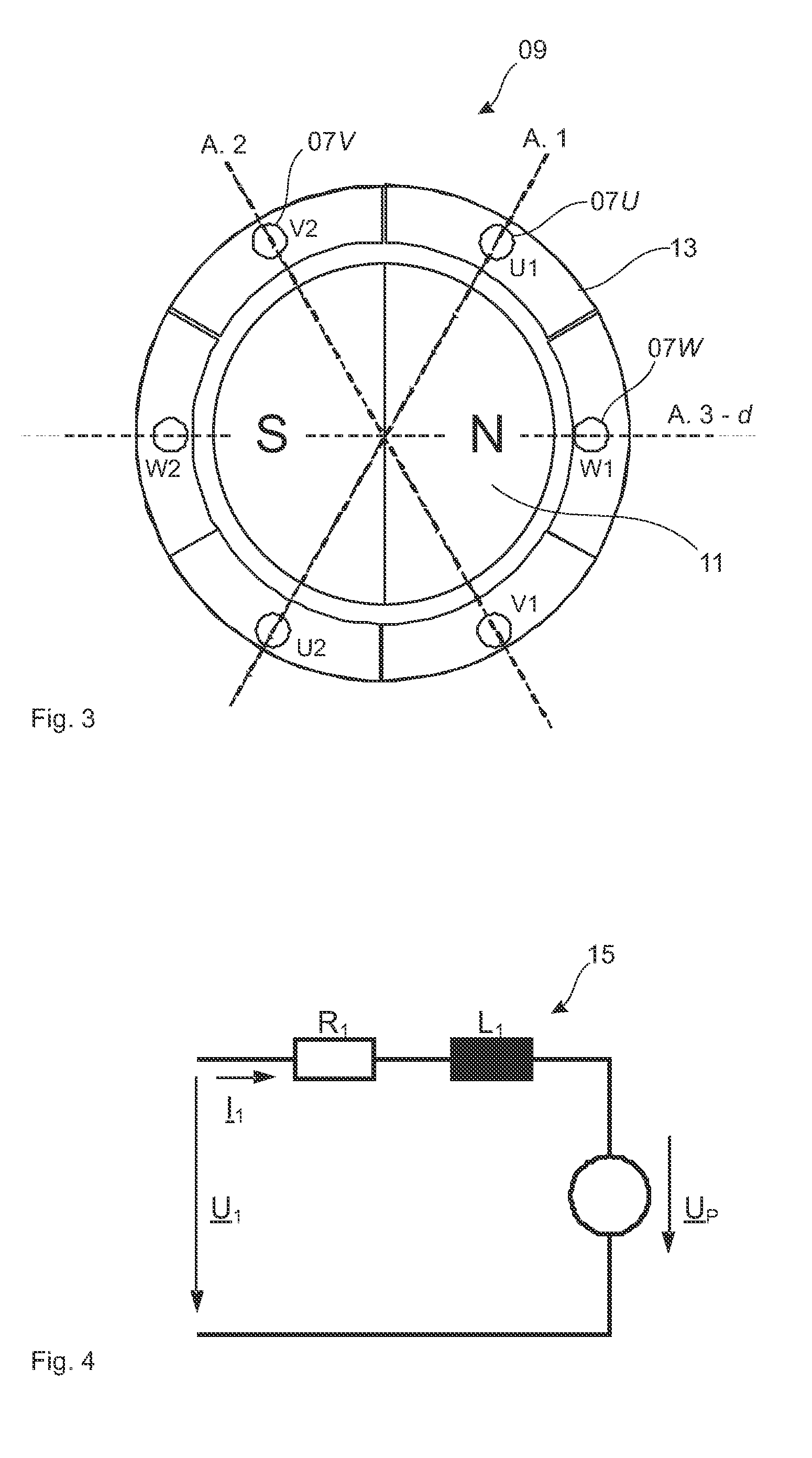
[0054]In order to explain the invention FIG. 1 shows an equivalent circuit of the stator coil 0103-phase motor. Each coil strand U, V and W comprises a resistor Rs 03 and a inductivity Ls 05. The three coil strands 07 are connected to each other at their first end and at their second end to the three phases U, V, W of the output of an inverter. The stator coil 01 integrates with the rotatably mounted rotor coil 11, that has a constant magnetization in a determination flux axial direction. The rotor magnetic field can be generated by permanent magnets attached along the circumference of the rotor or by a direct current in a rotor winding which direct current is supplied via slip rings. The rotor magnetic field adheres to the rotating stator magnetic field and thus allows the rotor to rotate in the frequency of the stator magnetic field. The system of rotor coil 11 and stator coil 01 can...


PUM


Abstract

Identification without shaft encoder of electrical equivalent circuit parameters of a three-phase asynchronous motor comprising: standstill position search of the rotor, so that the d flux axial direction of the rotor is aligned opposite the α axial direction of the stator; test signal voltage supply U1d in the d flux axial direction of the motor whereby the q transverse axial direction remains without current; measuring signal current I1d of the d flux axial direction of the motor; identification of equivalent circuit parameters of the motor based on the test signal voltage U1d and on the measuring signal current I1d in the d flux axial direction; whereby the rotor remains torque-free. The method used to control electrical drives. An identification apparatus for a synchronous motor and a motor control device comprising the apparatus, whereby identified equivalent circuit parameters can be used to determine, optimize and monitor a motor control.

Description

[0001]The present invention starts from a method, a device, an apparatus and the use of a method for an identification of electrical equivalent circuit parameters of a three-phase synchronous motor. Electrical equivalent circuit parameters make possible the characterization of a three-phase motor by electrical equivalent circuit components so that the electrical behavior of the motor can be simulated in operation.STATE OF THE ART[0002]Various methods are known from the state of the art for determining the electrical behavior of a three-phase motor. As a rule, direct current tests and short-circuit tests are performed on a motor in order to measure the electrical behavior in such operating scenarios and to be able to derive from it the electrical operating behavior for other operating instances. A three-phase synchronous motor comprises a stator with at least three stator coils and comprises a rotor with a permanent magnetization that is caused either by permanent magnets or is gener...

Claims


Application Information

Patent Timeline
IPC IPC(8): H02P6/20
CPCG01R31/34H02P23/14H02P2207/05H02P21/16
Inventor VILLWOCK, SEBASTIANZATOCIL, HEIKO
Owner BAUMULLER NURNBERG GMBH
Why Eureka
Try Eureka