
inertial type acoustic transducer

a transducer and inertial type technology, applied in the direction of transducer casings/cabinets/supports, electrical transducers, electrical apparatus, etc., can solve the problems of complex wiring of transducers from electrical subsystems used to drive and feed the transducer, complex and difficult mounting and installation,

Inactive Publication Date: 2012-02-16
KATZ ROBERT
View PDF9 Cites 12 Cited by
  • Summary
  • Abstract
  • Description
  • Claims
  • Application Information

AI Technical Summary

Benefits of technology

[0013]1) It is therefore an object of the present invention to provide a novel system whereby an inertial type audio transducer or an inertial type voice coil actuators (both hereinafter “transducer(s)”) can be installed and create sound without extraneous wires attached.2) It is further an object of this invention to create an inertial type audio transducer and integrate various subsystems therein to support their use.3) It is further an object of this invention to integrate an audio amplifier to the inertial type transducer and wireless source signal receiver to the inertial type transducer to permit ease of installation.4) It is further an object of this invention to integrate to the inertial type audio transducer an amplifier, its electrical power supply if required, and a wireless receiver for source and control information to be fed to the inertial type transducer's audio amplifier.5) It is an object of this invention to reduce the wiring required to cause the system to provide for simpler installation into difficult situations where installing additional wires is difficult or not possible;7) It is further an object of this invention to provide an inertial type transducer which requires only an electrical power feed to function while embedded in other structures and which does not need wires for transmission from its audio source.8) It is further an object of this invention to create a novel means by way of a systems approach, to resolve the problematic aspects of the audio system including installation, supply of source information, and amplification aspects of the above mentioned inertial type actuators;9) It is further an object of this invention to provide a means to integrate a wireless source and control receiver technology into an inertial type audio transducer in a fashion to optimize is functioning;10) Another object of this invention is to manage and dissipate heat produced by the transducer, so as to improve efficiency of the transducer, and ensure longevity.

Problems solved by technology

A disadvantage of the acoustic type actuator is that mounting and installing them to remain hidden can be complex and difficult.
Wiring the transducers from the electrical subsystems used to drive and feed the transducer is often so complex or difficult as to be prohibitive to the particular use.
Still, there are non-trivial problems that dictate that these solutions are incomplete and warrant a novel solution to better the momentum, or inertial type sound generating devices.
However, both the installation of the device and feeding the transducers with desired audio content can be difficult and problematic.
The problem arises when the sound generating devices or transducers are to be installed, by way of example, onto a product, or into an architectural edifice.
Running wires from the amplifier to the transducer can be prohibitive as the transducer devices are preferably hidden within the structures they are attached to.
Employing an integrated audio amplifier would save time and expense in the installation process.
The integration of the amplifier and preferably its power supply, into device structure or housing would be beneficial, but accomplishing the integration, in turn, raises new issues.
It is not beneficial to integrate the source for the amplifier into the transducer as the source would then be inaccessible to the user.

Method used


Image

  •  inertial type acoustic transducer
  •  inertial type acoustic transducer
  •  inertial type acoustic transducer

Examples


Embodiment Construction

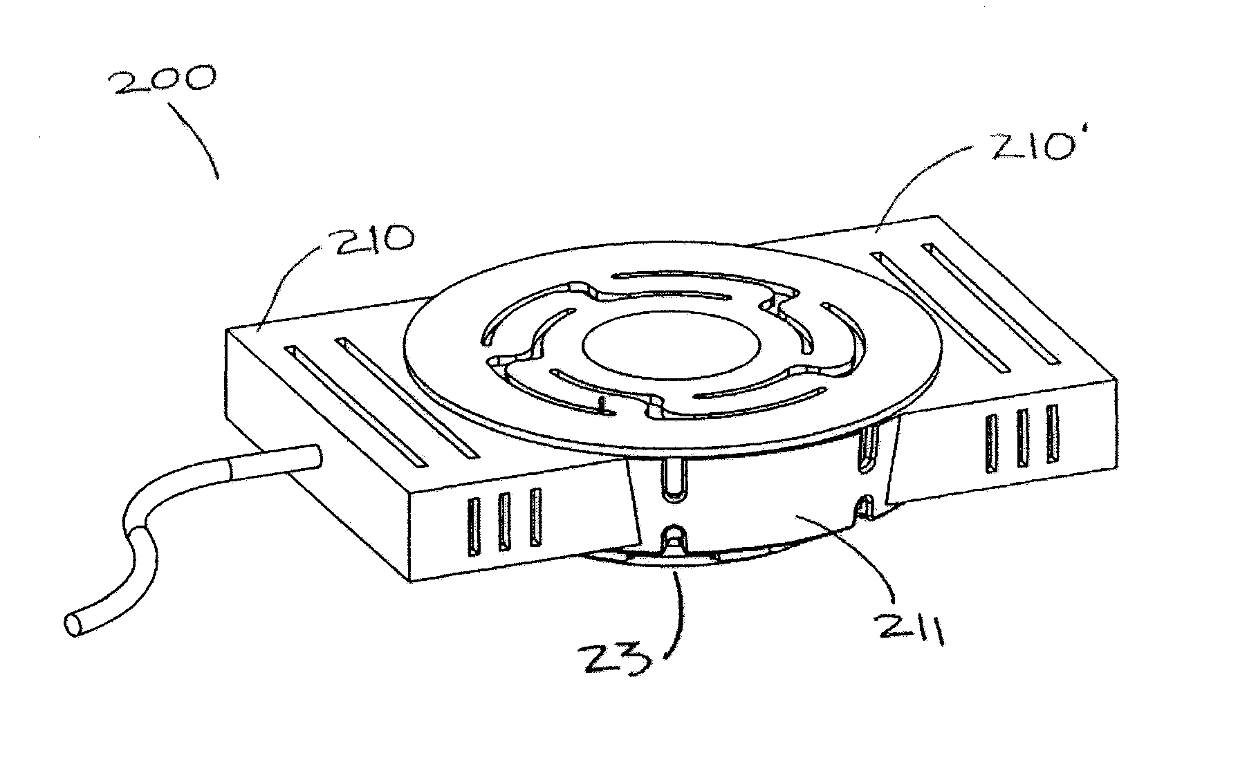
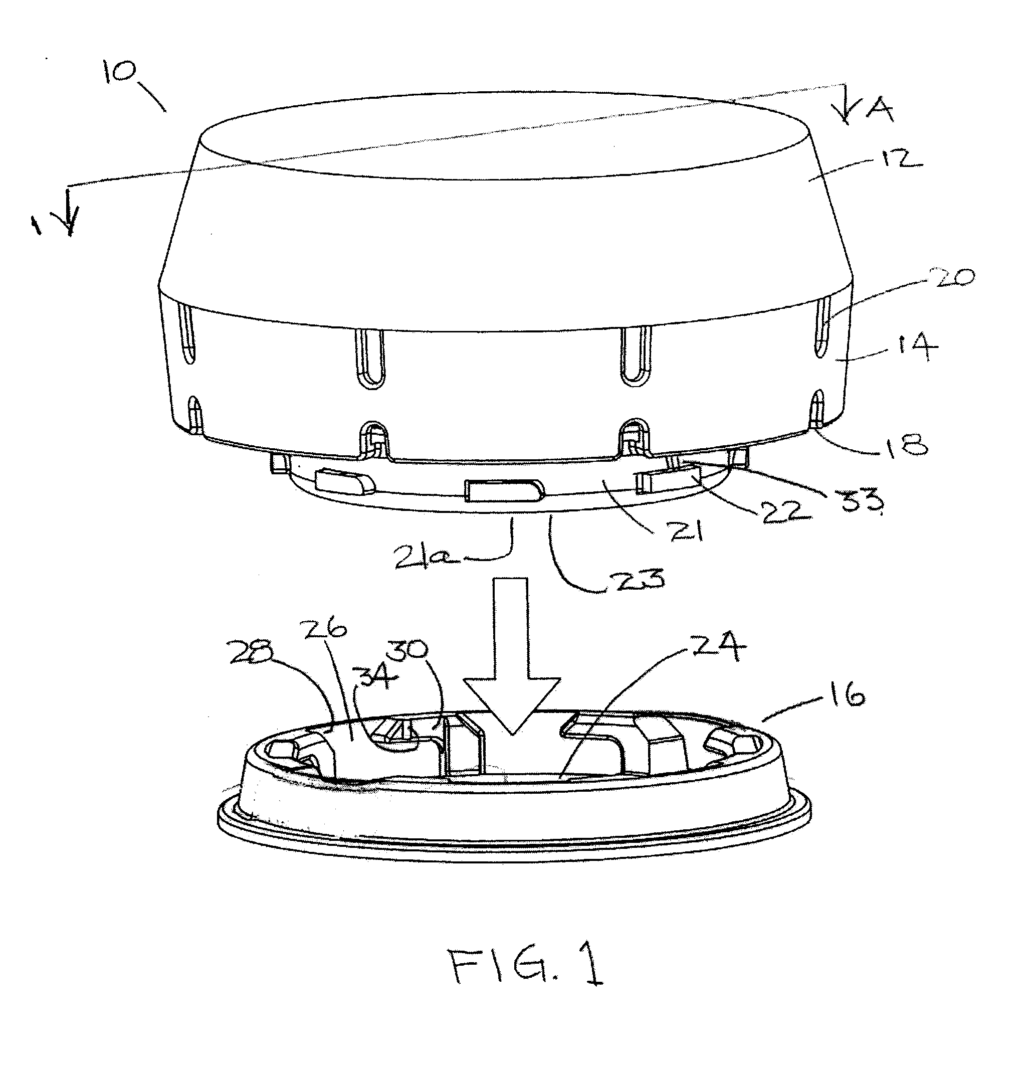
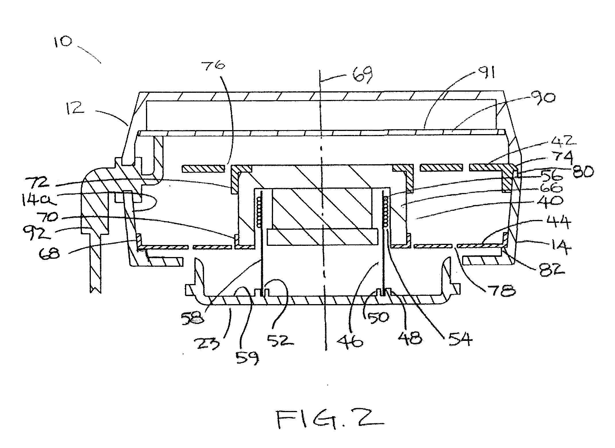
[0022]In the non-restrictive illustrative embodiment of the present invention a top perspective view of the present invention is illustrated in FIG. 1 which shows a cross section line AA through the center of the inertial type acoustic transducer 10. The transducer 10 is characterized by a housing, preferably an upper housing 12 and a lower housing 14. A means for mounting the transducer 16 lies beneath the transducer 10 and serves to mount the inertial type acoustic transducer 10 to a soundboard or substrate which functions as a sound emitter when energized by the acoustic transducer 10. Said means for mounting the transducer 16 may be affixed to a soundboard or substrate mechanically, adhesively or by other like means. The transducer upper housing 12 and lower housing 14 are further characterized by means to dissipate heat 18 and 20. In the preferred embodiment, said means to dissipate heat comprise a plurality of convective ventilation openings 18 and 20. Said plurality of openin...


PUM


Abstract

The present invention is drawn to inertial type transducers and a system for reducing the complexity and difficulty of installing the transducers internal to a structure. The transducer is equipped with a wireless receiver for receiving both sound content signals and control signals, and an amplifier, along with a power supply. Because the amplifier is activated by the wireless receiver, there are no wires necessary to connect the transducer to the source of the sound content or control signals thereby vastly simplifying installation. Heat dissipation and height minimization are also addressed.

Description

FIELD OF THE INVENTION[0001]The present invention relates generally to electrodynamic, inertial type acoustic transducers or other inertial type sound generating transducers and, more particularly, to momentum or inertial type voice coil actuators capable of converting energy between electrical and mechanical form and novel ways to permit them to be used.BACKGROUND OF THE INVENTION[0002]The development of the inertial type acoustic actuator field has been growing and advancing. These devices offer benefit over sound distributed by loud speakers because of their ability to radiate sound through substrates. The sound produced is more accurate and, in line with consumer demand, the intertial type acoustic actuator can be mounted in such a way as to employ a wall, ceiling, or even furniture as the substrate therefore becoming nearly if not completely “invisible” sound systems, or sound systems that can be hidden from view. A disadvantage of the acoustic type actuator is that mounting an...

Claims


Application Information

Patent Timeline
IPC IPC(8): H04R23/00
CPCH04R9/022H04R9/066H04R2420/07
Inventor KATZ, ROBERT
Owner KATZ ROBERT
Learn More