High temperature fiber optic turnaround

Inactive Publication Date: 2012-02-16
QOREX
View PDF4 Cites 13 Cited by
  • Summary
  • Abstract
  • Description
  • Claims
  • Application Information

AI Technical Summary

Benefits of technology

[0010]In another aspect of the present invention, a sensing cable is provided that includes sensing fibers having ends, a turnaround section spliced to the ends of the sensing fibers, an inner sleeve mounted to the sensing fiber and the turnaround section and having a terminating end in the area of the turnaround section, and an elongated outer armor casing, including an outer armor tube and a sealing cap, that encases the terminating end of the inner sleeve. The connections between the inner sleeve, the armor tube and the sealing cap are welded, which provides a robust pressure barrier. In addition, due to the compact size of the turnaround section, the size of the elongated armor casing can be decreased, which facilitates seamless install into downhole environments.
[0011]In an

Problems solved by technology

Between the stress of bending the fiber and the bend itself, the fiber often suffers from material integrity and optical loss issues.
However, the packaging or encasing process often occurs at high temperatures, which compounds the issues of material integrity and optical loss.
In addition, the fiber may be utilized in an environment in which high operating temperatures further compound the issues of material integrity and optical loss, and degrade the operating life of the sensing fiber.
However, the low temperature fiber optic approach has a limited

Method used


Image

  • High temperature fiber optic turnaround
  • High temperature fiber optic turnaround
  • High temperature fiber optic turnaround

Examples


Embodiment Construction

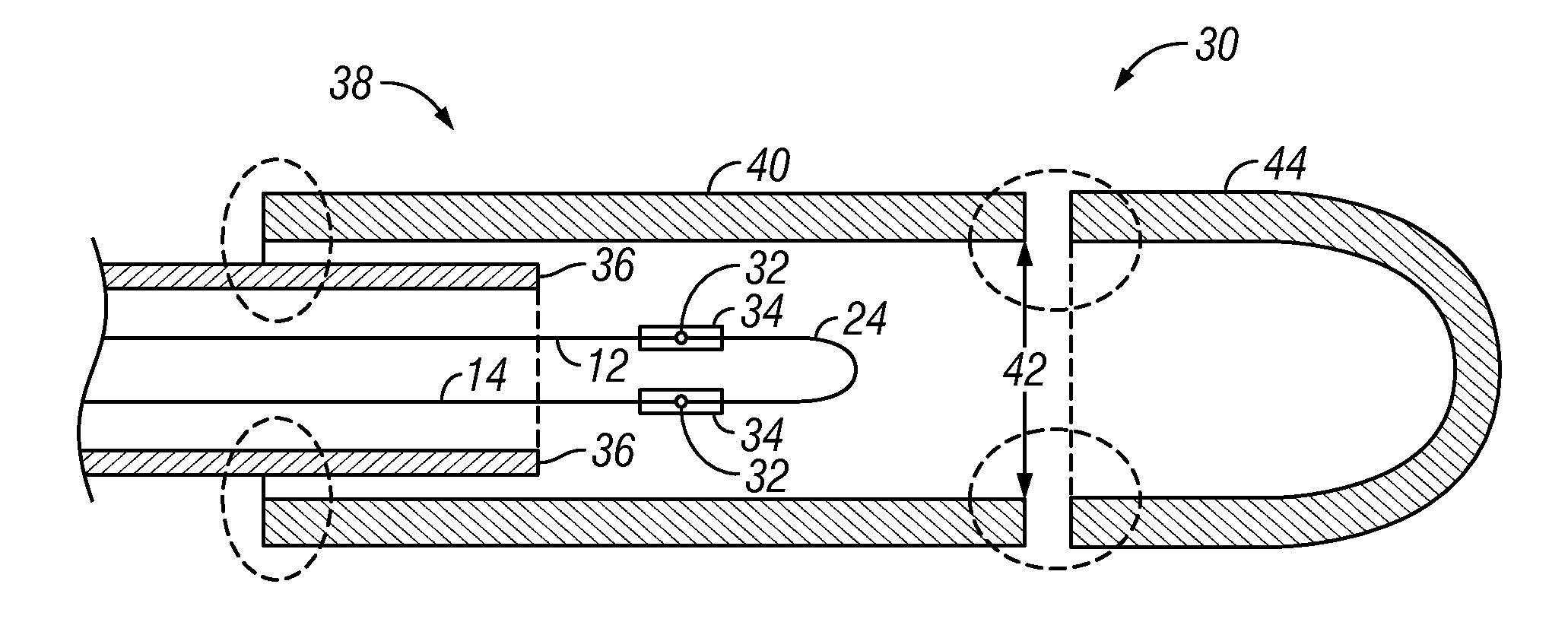
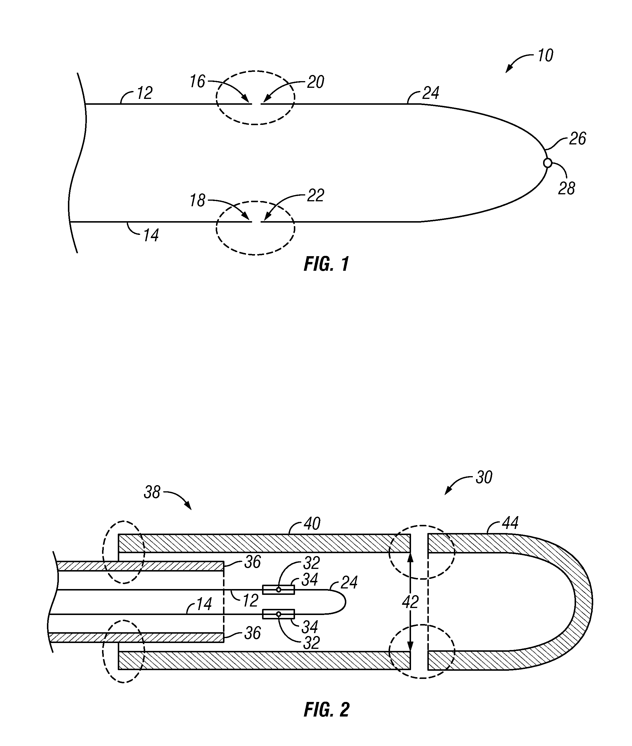
[0020]Referring to FIG. 1, the end portion of a sensing fiber assembly 10 is shown. The sensing fiber assembly 10 includes a pair of sensing fibers 12, 14 that run substantially parallel to one another and culminate in a substantially aligned pair of ends 16, 18. Each end 16, 18 is spliced to a pair of corresponding ends 20, 22 of a turnaround section 24. The joining of the sensing fibers 12, 14 via the turnaround section 24 creates a complete optical path down a first fiber 12, through the turnaround section 24 and back through the second fiber 14.

[0021]The turnaround section 24 includes a bend 26. The bend 26 has a small-radius (e.g., having a radius of between 0.05 and 0.200 inches and, in some embodiments, 0.1 inches), is U-shaped and forms an angle of substantially 180°. In some embodiments, the bend 26 is substantially elliptically shaped.

[0022]In some embodiments, the turnaround section 24 has a modal filter 28 formed integrally therein. The modal filter 28 selectively blocks...


PUM

PropertyMeasurementUnit
Temperatureaaaaaaaaaa

Abstract

A sensing cable includes a pair of sensing fibers that are connected to one another by a U-shaped turnaround section. The turnaround section is a section of sensing fiber coated with a jacket that includes metallic components. The turnaround section is bent and, then, annealed according to a method of the present invention. The turnaround section is robust and reduced in size (i.e., radius). The sensing cable also includes an inner sleeve that surrounds the sensing fibers and an elongated outer armor casing (i.e., including an armor tube and a sealing cap) that encases a terminating end thereof. The armor tube and the sealing cap protect the sensing fiber from mechanical and chemical harm, are reduced in size and facilitate insertion of the sensing cable into downhole environments. The sensing cable has improved operating range up to 300° C.

Description

CROSS REFERENCE TO RELATED PATENT DOCUMENTS[0001]The present application is a non-provisional of and claims the benefit of U.S. patent application Ser. No. 61 / 373,349 to MacDougall et al., and incorporates the following patent documents by reference: U.S. patent application Ser. No. 61 / 373,364 to MacDougall et al., entitled “METHOD FOR PERFORMING OPTICAL DISTRIBUTED TEMPERATURE SENSING (DTS) MEASUREMENTS IN HYDROGEN ENVIRONMENTS”; U.S. patent application Ser. No. 61 / 373,394 to MacDougall et al., entitled “PASSIVATION OF OPTICAL SENSING FIBERS”; and U.S. patent application Ser. No. 61 / 373,442 to MacDougall et al., entitled “LOW PROFILE, HIGH TEMPERATURE, HYDROGEN TOLERANT OPTICAL SENSING CABLE”.FIELD OF THE INVENTION[0002]The present invention generally relates to an optical sensing fiber cable and, more specifically, to a high temperature optical sensing fiber with an annealed turnaround and a casing, and a method of producing the same.BACKGROUND OF THE INVENTION[0003]Optical fibers...

Claims


Application Information

Patent Timeline
IPC IPC(8): G02B6/00C03B37/10
CPCG01K11/32G01K2011/324G02B6/4492G02B6/3827G01K11/324G02B6/44382
Inventor MACDOUGALL, TREVOR WAYNESANDERS, PAUL ERIC
Owner QOREX
Why Eureka
Try Eureka