Efficient Design and Configuration of Elements in a Process Control System

a control system and efficient design technology, applied in the field of process control networks, can solve the problems of large number of clicks, limited in usefulness to the specific process function, and difficult, if not impossible, to use a graphical program created to support a control operator in a context involving maintenance, configuration, or simulation functions,

Active Publication Date: 2012-02-16
FISHER-ROSEMOUNT SYST INC
View PDF26 Cites 70 Cited by
  • Summary
  • Abstract
  • Description
  • Claims
  • Application Information

AI Technical Summary

Benefits of technology

[0009]A software system for configuring, supervising, or troubleshooting a process control system includes an intuitive task-based user interface that conveniently organizes visual and textual controls for the available functionality. The user interface reduces the number of time of “clicks” or other commands required to access the desired functionality, positions the controls in intuitive and convenient locations, reduces the number of windows necessary to depicting desired information, displays controls relevant to a particular context, presents visual cues to the user for quick identification of the desired option or control, implements techniques for effectively visualizing control strategies, and improves the overall convenience of using the software system. The software system may support, for example, functionality of configuring the process control system, viewing configuration of the process control system, downloading control modules to controllers and physical devices, defining control logic for continuous and batch control, creating and editing product recipes in a process control system, controlling batch execution according to these recipes, exploring or viewing plant equipment, or any combination thereof. In some embodiments, the software system is an application suite that includes several applications, each adapted to support a respective set of engineering activities. For example, the software suite in one embodiment includes an explorer application for configuring a process plant, viewing and updating configuration of the process plant, downloading control modules to physical entities, etc.; a control studio application for designing control strategies for use in the process plant; and other applications. Each of the applications included in the software suite includes a respective user interface.
[0010]In an embodiment, the user interface of the explorer application supports a main content pane in which the explorer applications provides a detailed view of one or several selected items such as physical devices operating in the process plant, logical structures such as control strategies defined using Fieldbus function blocks, for example, process parameters associated with a selected physical or logical entity, configuration parameters applicable to devices and control strategies and stored in the corresponding databases, etc. The user interface further supports at least some of a navigation pane to display various controls and indicators to permit users to more easily locate and select various physical and logical entities in the process plant; a status bar to display the status of an operation; an address bar to specify a current location; a preview pane to provide a graphic and / or text reduced in quality and size to the user; a details pane to provide a detailed depiction of physical or logical entity; an instant search pane to support searching through one or several configuration database, run-time data, recipes, and other content; and a command bar in which the explorer application provides controls for performing engineering tasks.

Problems solved by technology

However, these graphical display applications have, in the past, been separately created as part of, or to independently support the specific applications with which they are associated, and thus are generally limited in usefulness to the specific process function for which they were created.
For example, it is difficult, if not impossible, to use a graphical program created to support a control operator in a context involving maintenance, configuration, or simulation functions.
Further, the existing applications typically require a large number of clicks of selections to reach a desired menu item.
In many cases, controls for triggering tasks are not organized in an intuitive manner, and accordingly require a significant amount of time to master.
In another aspect, the ever-increasing number of command options and features continues to make process control design, configuration, and management more complex.

Method used


Image

  • Efficient Design and Configuration of Elements in a Process Control System
  • Efficient Design and Configuration of Elements in a Process Control System
  • Efficient Design and Configuration of Elements in a Process Control System

Examples


Embodiment Construction

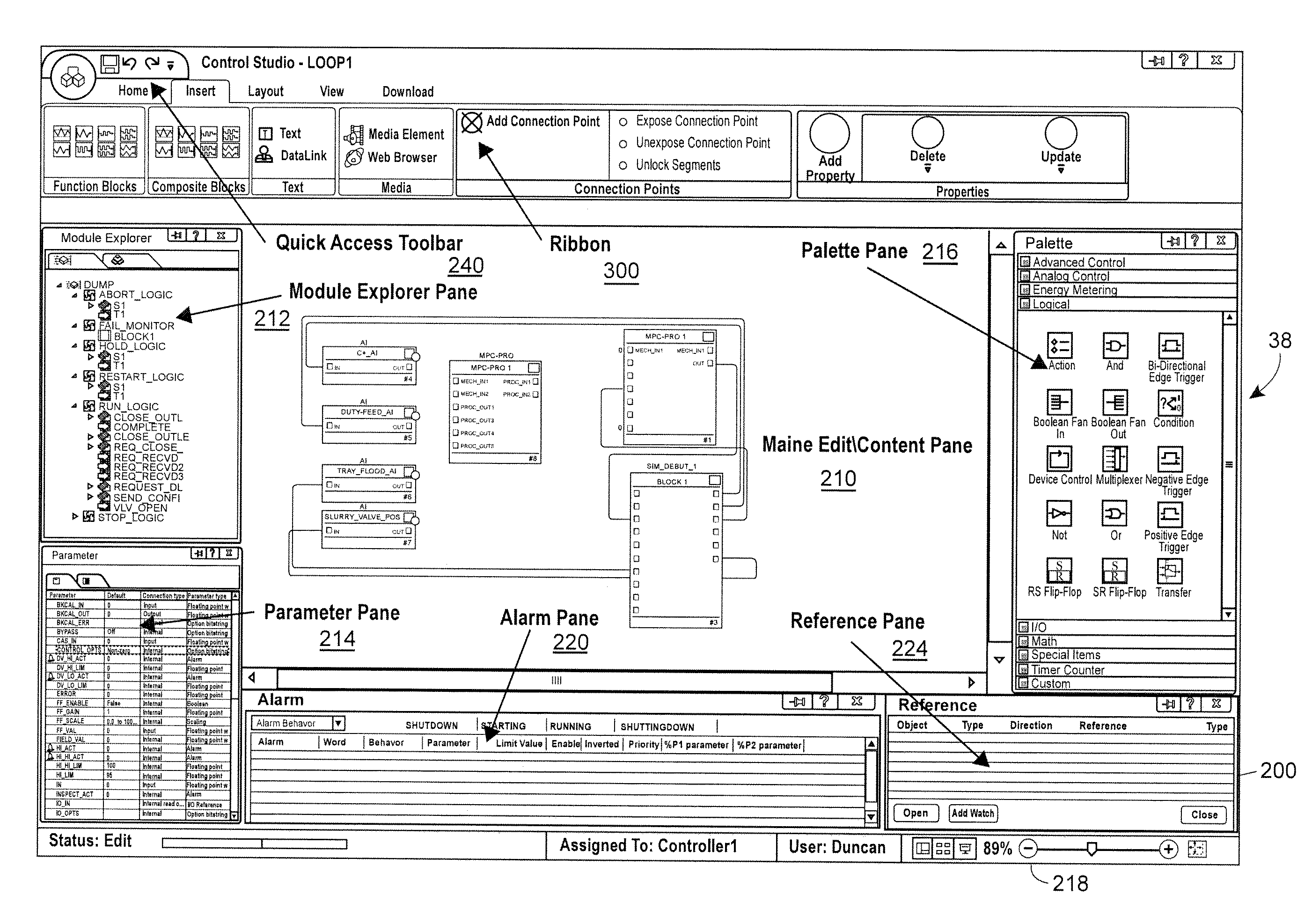
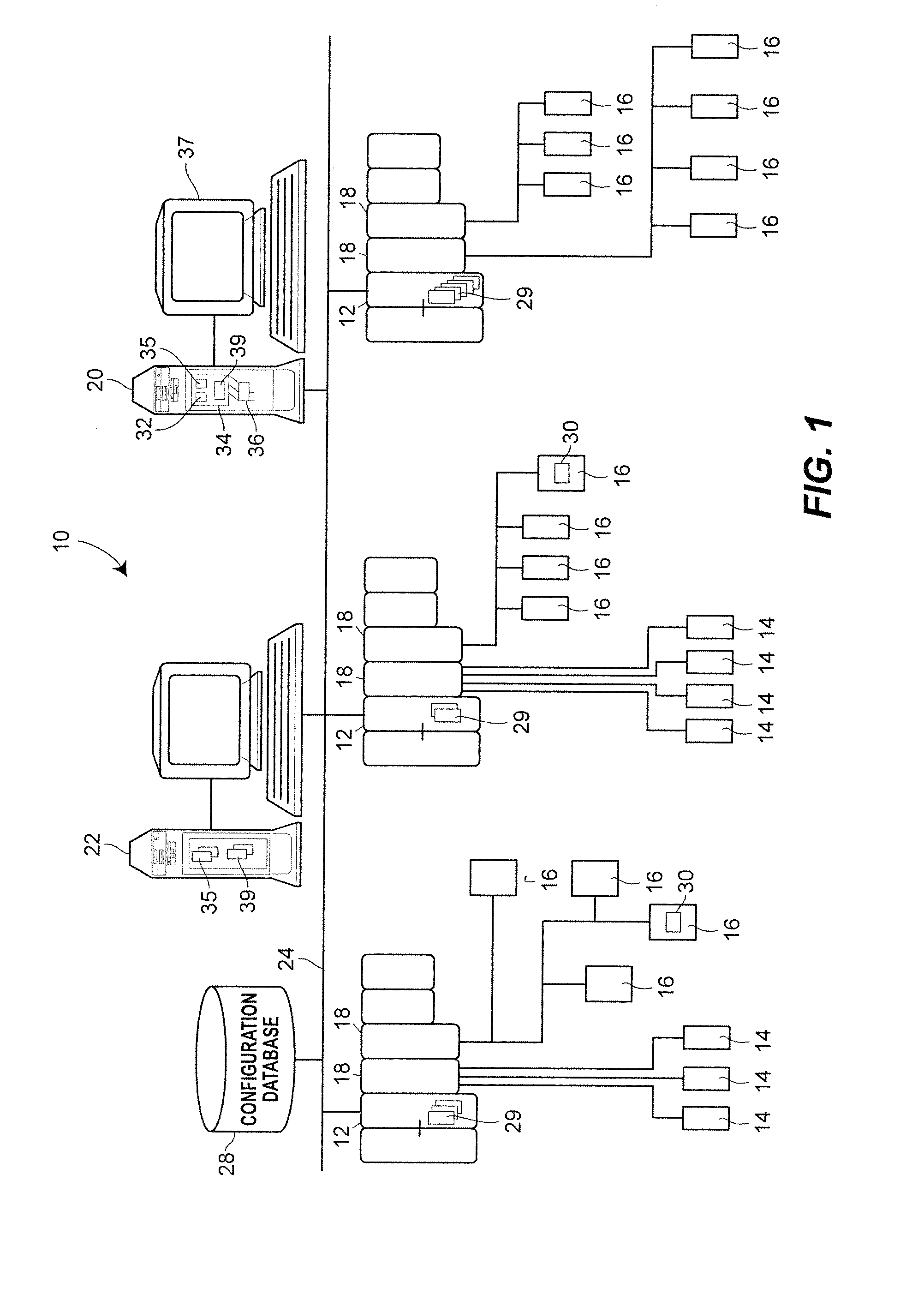
[0055]A software-based process control system for defining, editing, and debugging control strategies, supervising the operation of a process plant in which control strategies are implemented, managing equipment, and performing other activities may include an interactive user interface for use by people engineers, operators, maintenance personnel. By providing context-specific dynamic menus, intuitive control items, configurable layout of panes, etc., the user interface reduces the time required to perform a desired task in the process control environment. Further, by supporting multi-pane editing and implementing techniques for generating visible connectors spanning multiple panes or deferring and linking parameters during recipe configuration, to consider just two examples, the user interface simplifies various engineering tasks and improves the overall user experience. An example process control system in which the user interface may be implemented is discussed first with referen...


PUM


Abstract

A process control configuration method in a user interface of a computer system for developing control strategies of a process plant, where the user interface defines a screen area to display a plurality of independent panes therein, includes generating a first edit pane, including displaying a graphical representation of a first set of logical or physical entities for carrying out respective process control operations in the process plant; generating a second edit pane, including displaying a graphical representation of a second set of logical or physical entities for carrying out respective process control operations in the process plant, wherein each in the first set and the second set of logical or physical entities includes at least one input and at least one output, and wherein each of the first edit pane and the second edit pane defines an independent user interface screen within the screen area; receiving a first selection of an output of a first entity in the first set of logical or physical entities; receiving a second selection of an input to a second entity in the first second of logical or physical entities; and automatically generating respective visual indicators in each of the first edit pane and the second edit pane in response to receiving the first selection and the second selection, wherein the visual indicators depict respective endpoints of a connection between the first entity and the second entity.

Description

CROSS-REFERENCE TO RELATED APPLICATION[0001]This application claims the benefit of U.S. Provisional Patent Application No. 61 / 101,055, entitled “User Interface for Configuring a Process Control System,” filed Sep. 29, 2008, the disclosure of which is hereby expressly incorporated herein by reference.FIELD OF TECHNOLOGY[0002]The present invention relates generally to process control networks and, more particularly, to a user interface for configuring various components and services in a process control environment.DESCRIPTION OF THE RELATED ART[0003]Distributed process control systems, like those used in chemical, petroleum or other processes, typically include one or more process controllers communicatively coupled to one or more field devices via analog, digital or combined analog / digital buses. The field devices, which may be, for example, valves, valve positioners, switches and transmitters (e.g., temperature, pressure, level and flow rate sensors), are located within the process...

Claims


Application Information

Patent Timeline
Patent Type & Authority Applications(United States)
IPC IPC(8): G05B19/02
CPCG05B19/0426G05B19/41865G05B2219/32097G05B2219/31396G05B2219/23258G05B19/41845G06F3/0484Y02P90/02G05B19/409G05B19/418G06F8/30
Inventor JONES, BRYAN MICHAELBELLVILLE, KEITH R.BALENTINE, JAMES R.SCHLEISS, TREVOR D.FELLOWS, HUBBARD F.
Owner FISHER-ROSEMOUNT SYST INC
Why Eureka
Try Eureka