Off-resonance frequency operation for power transfer in a loosely coupled air core transformer

a technology of air core transformer and power transfer, which is applied in the direction of mechanical energy handling, electric devices, transportation and packaging, etc., can solve the problems of heavy weight of the transformer with the ferromagnetic core, and achieve the effect of high efficiency, high transfer efficiency and fast maximum transfer efficiency

Active Publication Date: 2012-02-23
UT BATTELLE LLC
View PDF10 Cites 30 Cited by
  • Summary
  • Abstract
  • Description
  • Claims
  • Application Information

AI Technical Summary

Benefits of technology

[0009]To date, most investigations on inductive power transfer through transformers have focused on getting the highest power level of load power, which occurs at resonance, and then optimizing the transfer efficiency at that resonant point. Investigations leading to the present disclosure have shown, however, that the highest transfer efficiency does not occur at a resonant frequency of a transformer. Thus, it is possible to achieve the highest efficiency in a transformer first and subsequently determining additional parameters needed to achieve the desired level of output power. Specifically, near maximum transfer efficiency is achieved by operating a transformer below the resonant frequency. An inductively coupled power transfer system can be configured so that the alternating current power source provides alternating voltage at an operating frequency in a range from 50% to 95% of the resonant frequency. Because the operating frequency is significantly offset from the resonance frequency, other receiving components in the secondary circuit located in the vicinity of the load couple less with the primary circuit, and therefore draws less power from the primary circuit. By deliberately avoiding maximum load power achievable at resonance, it is possible to provide an inductively coupled power transfer system with enhanced transfer efficiency.

Problems solved by technology

Thus, transformers with a ferromagnetic core tend to be heavy, in addition to being costly to manufacture.

Method used


Image

  • Off-resonance frequency operation for power transfer in a loosely coupled air core transformer
  • Off-resonance frequency operation for power transfer in a loosely coupled air core transformer
  • Off-resonance frequency operation for power transfer in a loosely coupled air core transformer

Examples


Embodiment Construction

[0023]As stated above, the present invention relates to apparatus and methods for transmitting power in a loosely coupled air core transformer at an off-resonance operational frequency, which are now described in detail with accompanying figures. It is noted that like and corresponding elements mentioned herein and illustrated in the drawings are referred to by like reference numerals.

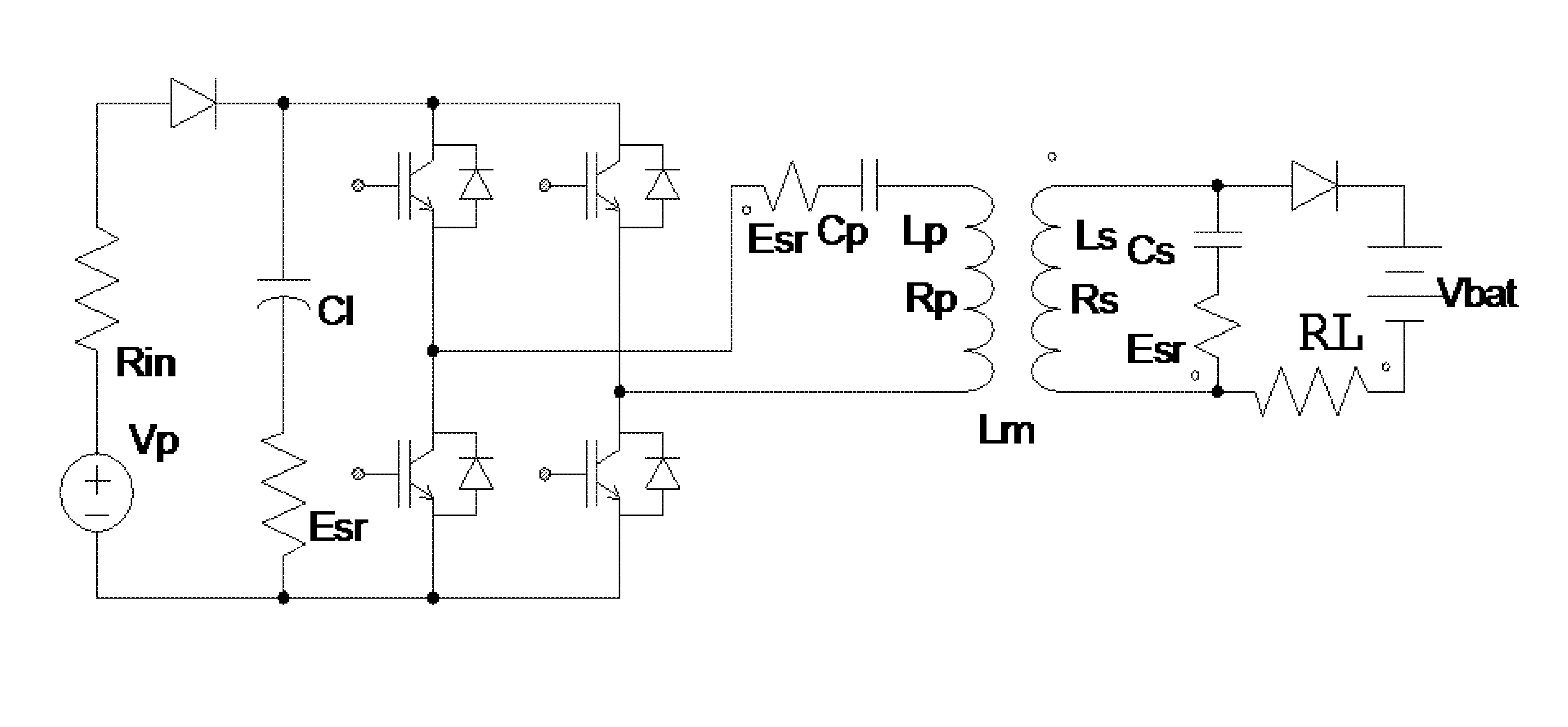
[0024]The circuit of the present disclosure is configured to select an operational frequency that is not a resonance frequency of a primary circuit of a loosely coupled air core transformer. In order to illustrate the operation of the circuit of the present disclosure, various exemplary circuits with a variable frequency power source are considered for their operational characteristics.

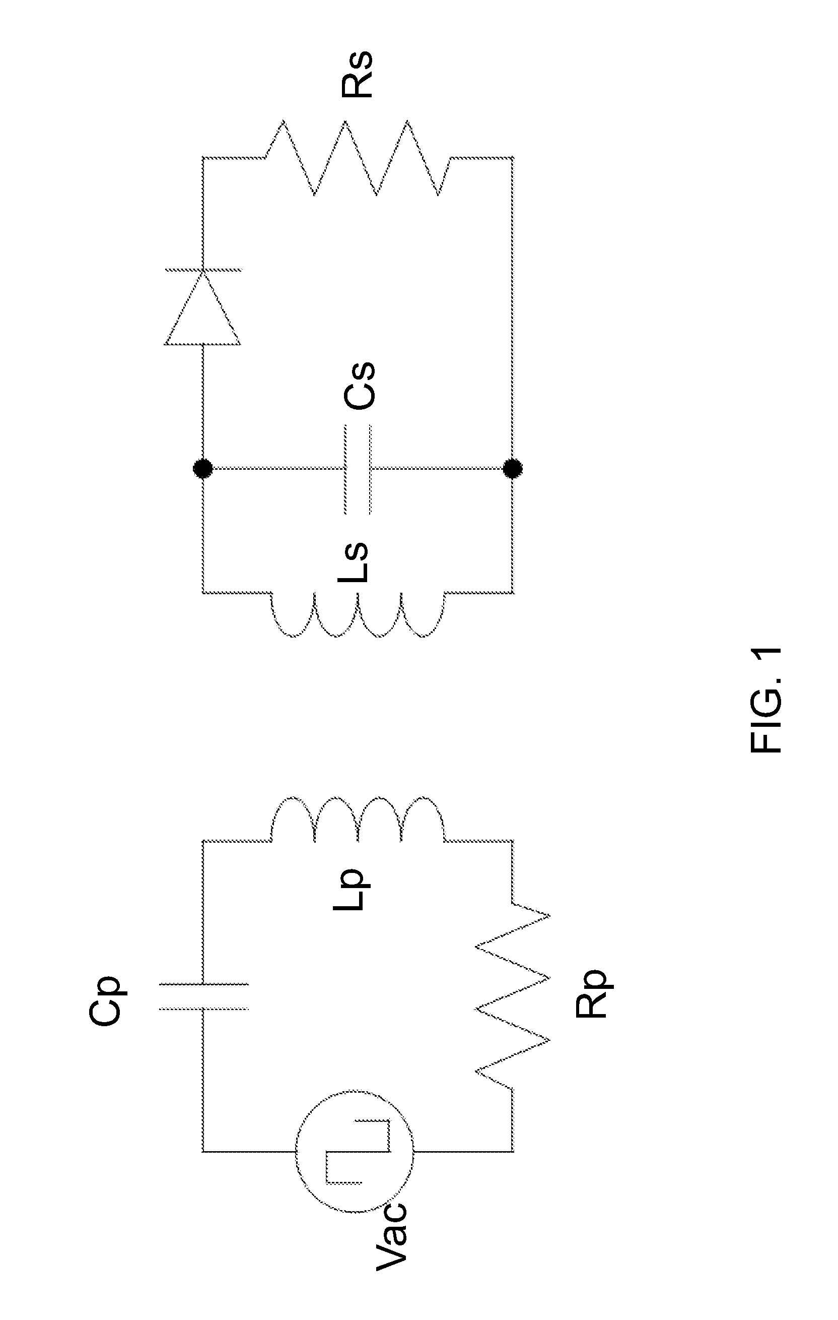
[0025]Referring to FIG. 1, a first exemplary air core transformer circuit includes a primary circuit located on the left side and a secondary circuit located on the right side. The series input impedance of the primary c...


PUM


Abstract

A power transmission system includes a loosely coupled air core transformer having a resonance frequency determined by a product of inductance and capacitance of a primary circuit including a primary coil. A secondary circuit is configured to have a substantially same product of inductance and capacitance. A back EMF generating device (e.g., a battery), which generates a back EMF with power transfer, is attached to the secondary circuit. Once the load power of the back EMF generating device exceeds a certain threshold level, which depends on the system parameters, the power transfer can be achieved at higher transfer efficiency if performed at an operating frequency less than the resonance frequency, which can be from 50% to 95% of the resonance frequency.

Description

STATEMENT REGARDING FEDERALLY SPONSORED RESEARCH OR DEVELOPMENT[0001]This invention was made with United States government support under Prime Contract No. DE-AC05-00OR22725 awarded by the U.S. Department of Energy. The United States government has certain rights in this invention.FIELD OF THE INVENTION[0002]The present invention relates to the field of inductive power transmission, and particularly to apparatus and methods for transmitting power in a loosely coupled air core transformer at an off-resonance operational frequency to achieve higher transfer efficiency than the transfer efficiency at resonance frequency.BACKGROUND OF THE INVENTION[0003]A transformer transfers electrical energy from one circuit to another through inductively coupled conductors, which are the coils. A change in current in a primary coil of a first circuit generates a time-dependent magnetic flux through a secondary coil in a second circuit. One of Maxwell's four equations provides:∇×E=-∂B∂t,which can be ...

Claims


Application Information

Patent Timeline
Patent Type & Authority Applications(United States)
IPC IPC(8): H02J7/10B60L1/00
CPCH01F38/14H02M3/3376H02J7/025H02J5/005H02J7/00712H02J50/12
Inventor SCUDIERE, MATTHEW B.
Owner UT BATTELLE LLC
Why Eureka
Try Eureka