Speckle removal for a laser scanning projector

a laser scanning and projector technology, applied in the field of speckle removal for laser scanning projectors, can solve the problems of preventing the resolution of successive pulses, serious limitations in the bandwidth of optical fibres, and difficulty in providing mathematical expressions for every, so as to reduce the visibility of speckles, and reduce the coherence length

Inactive Publication Date: 2012-02-23
OPTYKA
View PDF1 Cites 11 Cited by
  • Summary
  • Abstract
  • Description
  • Claims
  • Application Information

AI Technical Summary

Benefits of technology

[0019]In accordance with a first aspect of the present invention there is provided an apparatus for reducing visibility of speckle in coherent light comprising multimode optical waveguide means arranged to propagate the coherent light therethrough to reduce a coherence length of the coherent light by intermodal dispersion and vibratable membrane mirror means arranged to reflect the coherent light either before or after passing through the multimode optical fibre means further to reduce the coherence length by distributing wave packets across different propagating modes and to erase the modal structure by averaging the distribution of energy across the modes leading to a more uniform illumination.
[0028]According to a second aspect of the invention, there is provided a method of reducing visibility of speckle in coherent light comprising: propagating the coherent light through multimode optical waveguide means arranged to reduce a coherence length of the coherent light by intermodal dispersion; and reflecting the coherent light from a vibratable membrane mirror means either before or after passing through the multimode optical waveguide means further to reduce the coherence length by distributing wave packets across different propagating modes and to erase the modal structure by averaging the distribution of energy across the modes leading to a more uniform illumination.

Problems solved by technology

It is generally difficult to provide a mathematical expression for every propagating mode when a fibre is multimode.
This phenomenon is known as intermodal dispersion and normally causes a serious limitation to the bandwidth of an optical fibre.
If not taken into account, this phenomenon prevents resolution of successive pulses.

Method used


Image

  • Speckle removal for a laser scanning projector
  • Speckle removal for a laser scanning projector
  • Speckle removal for a laser scanning projector

Examples


Embodiment Construction

[0053]In accordance with the present invention the energy of a wave train is distributed over a plurality of modes of a multimode optical fibre in such a way that intermodal dispersion creates sufficient time delay between the set of modes significantly to reduce speckle contrast, where speckle contrast is defined as the ratio of the standard deviation of the intensity to the mean of the intensity across a coherently illuminated area.

[0054]It is usually accepted that, for light emission of spectral line width Δv, or Δλ centered around λ, the coherence time tc is approximately:

tc≅1Δv=λ2_cΔλ

[0055]The following table records typical linewidth values and associated coherence times for different laser technologies.

LinewidthCoherence timeMode locked gas3MHz300nslaserMulti longitudinal0.5GHz2nsmode gas laserDPSS laser0.1 nm (~0.1 THz @ 532 nm)10psDiode laser1 nm (~1 THz @ 532 nm)1ps

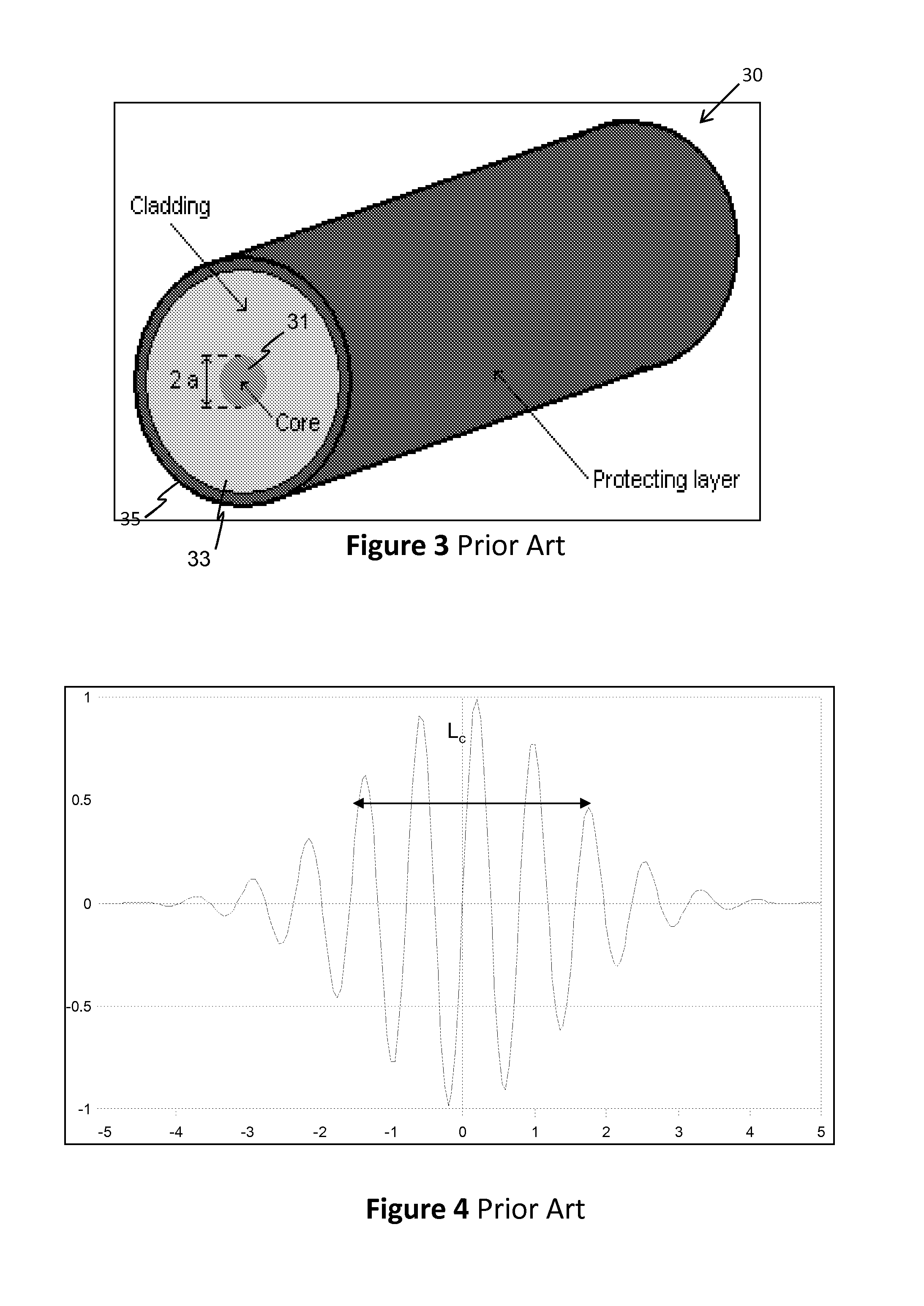
[0056]FT400EMT is a commercial optical fibre available from InnovaQuartz the characteristics of which are as ...


PUM


Abstract

An apparatus and method for reducing the visibility of speckle in coherent light comprises propagating the coherent light through a multimode optical waveguide 106 to reduce a coherence length of the coherent light by intermodal dispersion. A vibratable membrane mirror 104 is arranged to reflect the coherent light either before or after passing through the multimode optical fibre further to reduce the coherence length by distributing wave packets across different propagating modes and to erase the modal structure by averaging the distribution of energy across the modes leading to a more uniform illumination. The invention may be used for speckle removal in a laser scanning projector.

Description

[0001]This invention relates to an apparatus and method for reducing the visibility of speckle and in particular to a laser scanning projector with speckle removal.BACKGROUND[0002]The guiding of optical radiation by waveguides such as planar waveguides or optical fibres is well known. While planar waveguides have a wide range of structures and geometries, as illustrated in FIGS. 2a to 2f, optical fibres, as shown in FIG. 3, usually have a circular transverse cross-section. FIGS. 2a to 2f show a sample of classical “simple” planar waveguide geometries; more complex variations of these are widely used to perform integrated optical functions such as coupling and switching. Optical waveguides rely on total internal reflection at an interface between two media of different refractive index to confine light within their cores. A wide range of materials from silica to polymers have been used to manufacture optical waveguides providing a range of properties.[0003]Referring to the cross-sect...

Claims


Application Information

Patent Timeline
Patent Type & Authority Applications(United States)
IPC IPC(8): G02B27/48
CPCG02B27/48H01S3/005
Inventor SQALLI, OMARDESCHARMES, NICOLAS
Owner OPTYKA
Why Eureka
Try Eureka