
MODULAR REFRIGERATOR and ICEMAKER

Inactive Publication Date: 2012-03-01
RAFALOVICH ALEXANDER
View PDF7 Cites 31 Cited by
  • Summary
  • Abstract
  • Description
  • Claims
  • Application Information

AI Technical Summary

Benefits of technology

[0023]Yet another embodiment of the invention provides a refrigerator with an air fan to enhance heat transfer from the warm end of the heat pipe to the cooling recipient. Still another embodiment of the invention provides a refrigerator wherein the cooling recipient is equipped with a temperature sensor that sends a signal to stop the fan when the cooling recipient temperature reaches or drops below a set temperature.

Problems solved by technology

This arrangement doesn't allow any meaningful variation in the refrigerator compartments without redesigning of the sealed system.
It's hard to add a compartment, an icemaker, or to increase or reduce width and height of an existing compartment without considerable changes in the sealed system including redesign of airflow passages, evaporators, fans, and so on.
Another problem with existing refrigerators is diagnostics and repair.
It's almost impossible to find a refrigerant leak in the sealed system, if the leak is in foamed connection tubes.
It may also be very expensive to fix any dent in the walls or local damage of the compartment liner.
While designing a new refrigerator it's also complicated to position an icemaker in the cooling compartment.
Besides, there are a couple weaknesses in this design.
Even with well-developed fins on the cold end of the heat pipe heat transfer by natural convection considerably increases heat pipe temperature that, in turn, reduces efficiency.
Another weakness of U.S. Pat. No. 4,003,214 is in positioning the warm end of the heat pipe in a reservoir filled with water to be frozen.
It considerably complicates ice harvesting from the icemaker.

Method used


Image

  • MODULAR REFRIGERATOR and ICEMAKER
  • MODULAR REFRIGERATOR and ICEMAKER
  • MODULAR REFRIGERATOR and ICEMAKER

Examples


Embodiment Construction

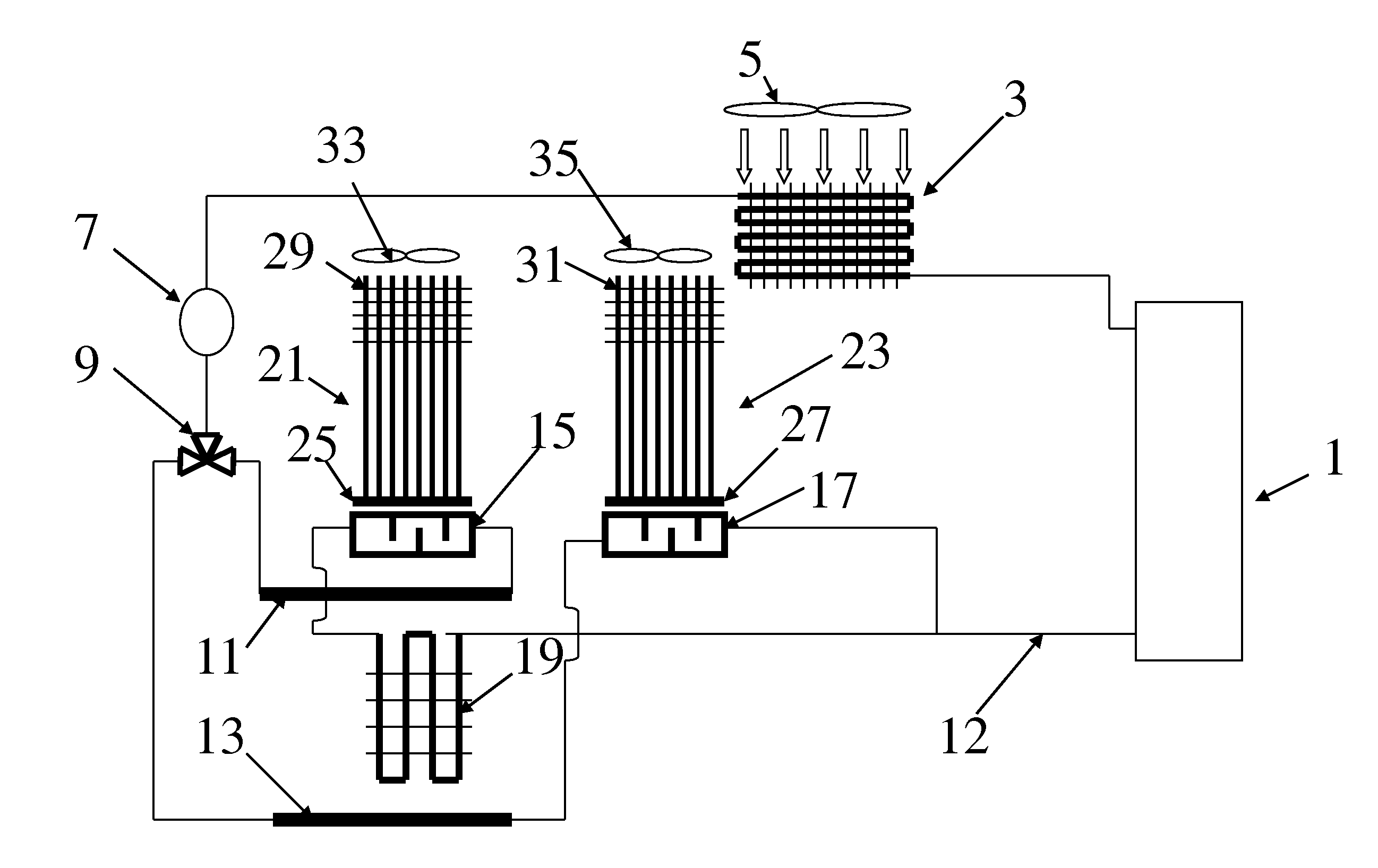
[0031]FIG. 1 shows sealed system schematics of a refrigerator with a heat pipe. Compressed gaseous refrigerant after compressor 1 flows to condenser 3 wherein high-pressure refrigerant cools down and condenses rejecting heat to airflow driven by fan 5. Liquid refrigerant through dryer 7 flows to multi-way valve 9. The valve depicted in FIG. 1 is a 3-way valve. However, it may be 2, 4, 5, N-way valve, or may be no valve at all. The 3-way step motor valve of Sanyo can be used as the 3-way valve depicted in FIG. 1. After valve 9 liquid refrigerant flows to expansion devices 11 and 13 that, for example, may be capillary tubes, and further to an evaporator that consists from several sections including cold plate sections 15, 17, and a conventional evaporating section 19. Cold plates 15, 17 are configured to have refrigerant flow therethrough to absorb heat and wherein at least a part of liquid refrigerant evaporates. Each cold plate section has a surface that is in heat transfer relation...


PUM


Abstract

A refrigerator includes a cabinet, a sealed system, a cooling recipient, and a heat pipe. To transport cooling capacity to the cooling recipient, evaporator in the sealed system includes a cold plate section with heat transfer surface. A cold end of the heat pipe is attached to the cold plate section of the evaporator. An internal refrigerating or freezing compartment, an external compartment, an ice maker, or an ice-making cabinet could be a recipient of cooling capacity. Air flowing around a warm end of the heat pipe brings cooling potential to the internal and / or external compartments. Icemaker and / or ice-making cabinet can be located in the freezing compartment, in the freezing compartment door, in refrigerating compartment, or in refrigerating compartment door. To facilitate heat transfer the warm end of the heat pipe is in heat transfer contact with an ice making cavity that receives and freezes water to ice. Depending on design and application an assembly of the cold plate section of the evaporator and the cold end of the heat pipe can be accessible either from inside or from outside of the refrigerator.

Description

BACKGROUND OF THE INVENTION[0001]The present invention relates to residential and commercial refrigerators, freezers, icemakers, and other cooling apparatuses.[0002]Main assembly in existing refrigerators and other cooling appliances consists of a sealed system, an insulated cabinet with one or several doors, and a control system. Basic parts of the sealed system include a compressor, a condenser, an expansion device that is often a capillary tube, an evaporator, and hermetically sealed connecting lines (tubes) delivering refrigerant to and from compressor, condenser, and evaporator. In addition, sealed system may be equipped with a drier, an accumulator and a receiver. Some sealed systems may have extra evaporators, expansion devices, compressors, condensers, and refrigerant valves. In medium and large refrigerators sealed system includes elements to provide airflow through condenser and evaporator.[0003]Refrigerator may also include an icemaker whereto cooling potential is deliver...

Claims


Application Information

Patent Timeline
IPC IPC(8): F25D11/00F25D17/06F25C1/00F25D23/02
CPCF25B5/00F25B23/006F25D11/025F28D2021/0071F28D15/0275F25B2600/2511F25C2400/10F25D23/04F25C5/22
Inventor RAFALOVICH, ALEXANDER
Owner RAFALOVICH ALEXANDER
Features
  • Generate Ideas
  • Intellectual Property
  • Life Sciences
  • Materials
  • Tech Scout
  • Unparalleled Data Quality
  • Higher Quality Content
  • 60% Fewer Hallucinations
Learn More