
Highly sensitive capacitive sensor and methods of manufacturing the same

a capacitive sensor, high-sensitivity technology, applied in the direction of speed/acceleration/shock measurement, measurement devices, instruments, etc., can solve the problems of non-linear displacement of the proof mass, significant damping effect, and non-linear relationship between the change, so as to achieve the effect of negligible effect on the linearity relatively high standing capacity of the micro-machined capacitive sensor

Inactive Publication Date: 2012-03-01
MEMSIC
View PDF10 Cites 22 Cited by
  • Summary
  • Abstract
  • Description
  • Claims
  • Application Information

AI Technical Summary

Benefits of technology

[0008]In accordance with the present application, micro-machined capacitive sensors implemented in micro-electro-mechanical system (MEMS) processes are disclosed that have high sensitivity, while providing an increased linear capacitive sensing range.
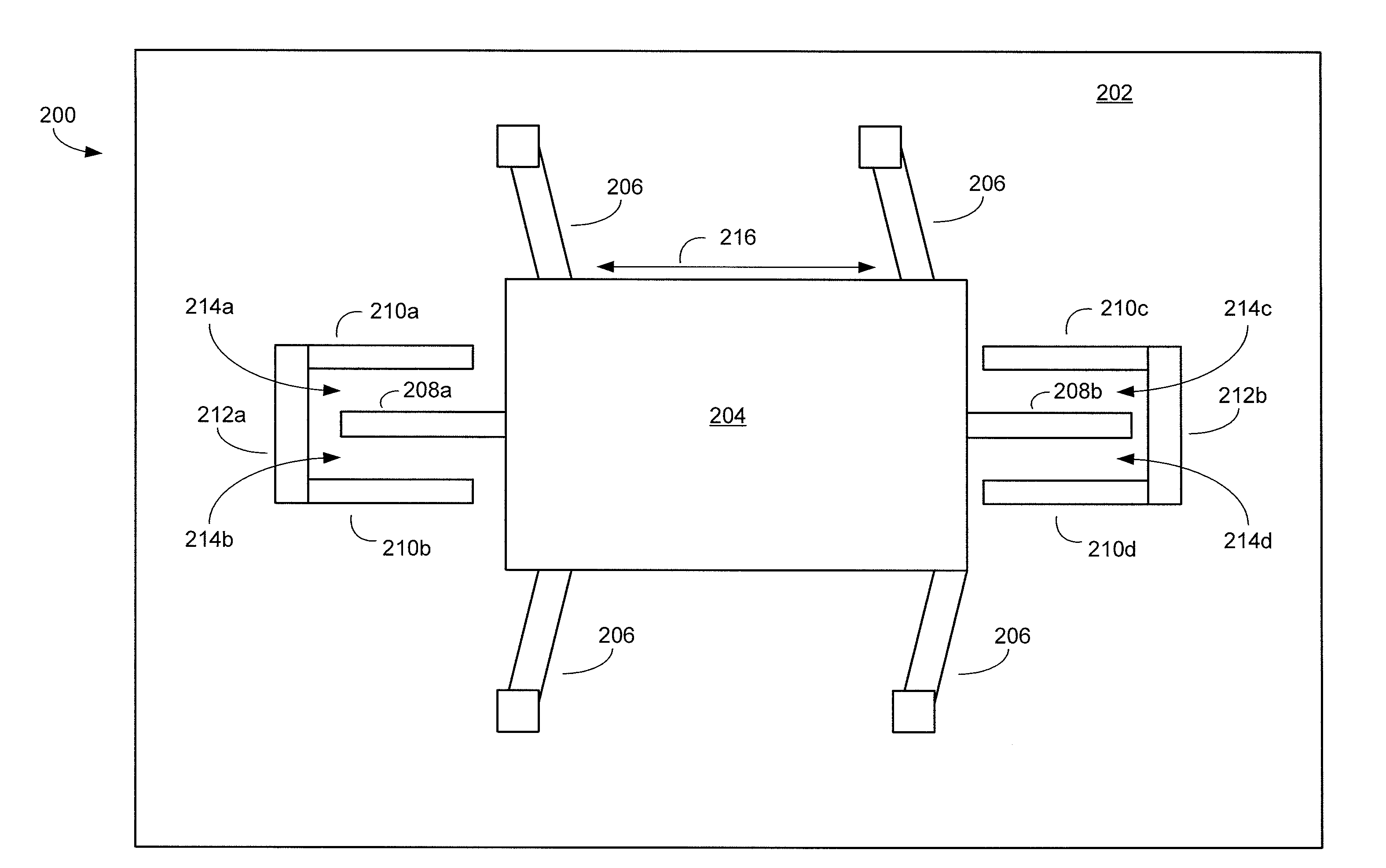
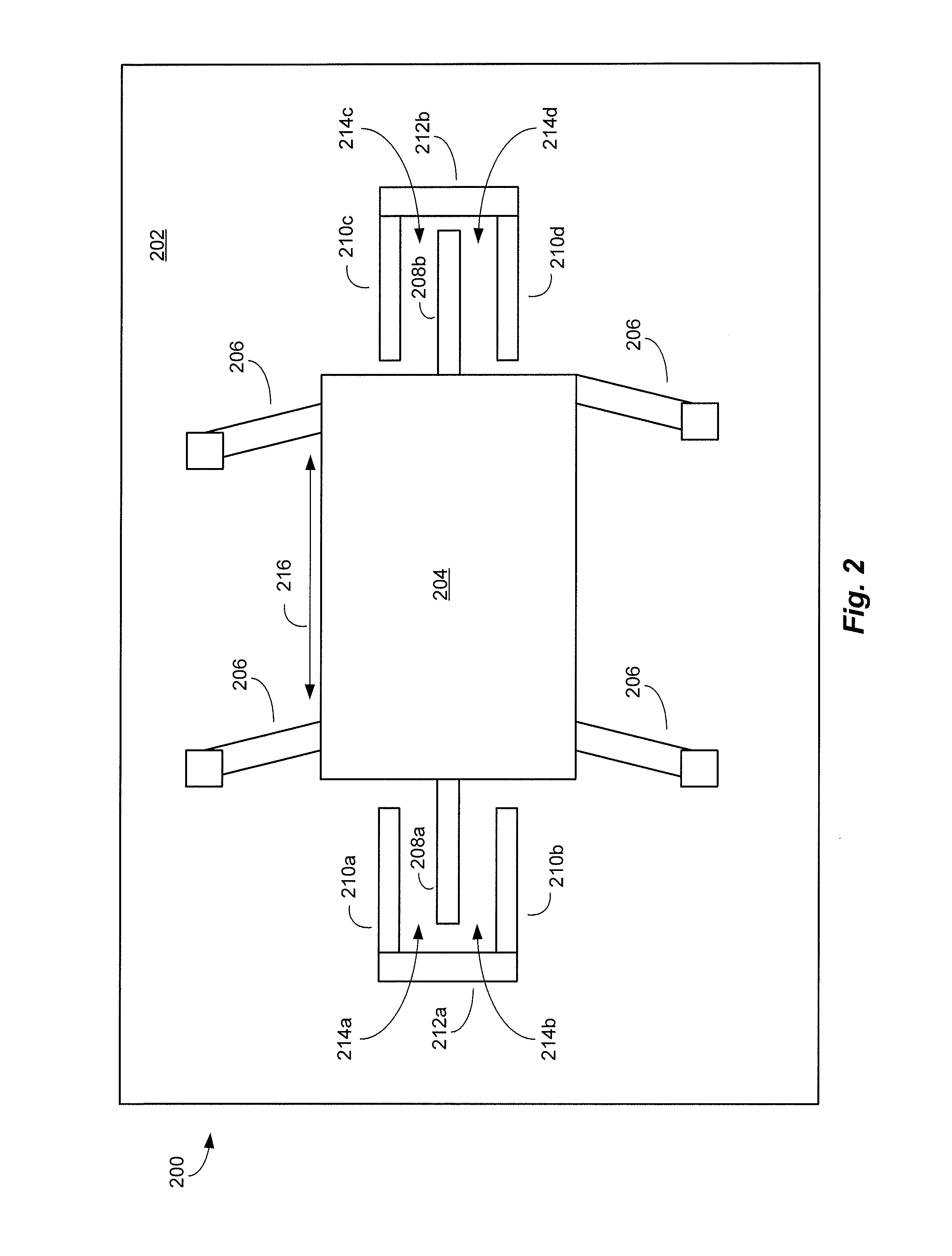
[0011]In accordance with a further exemplary aspect, both the finger and the electrode in the finger / electrode pair have rectangular tooth profiles that include at least two substantially rectangular teeth. Because changes in the overlapping area of the finger and the electrode are multiplied by the number of rectangular teeth, while the standing capacity of the micro-machined capacitive sensor remains relatively high, the sensitivity of the disclosed micro-machined capacitive sensor employing variable-area sensing is significantly increased per unit area of the finger and the electrode.

Problems solved by technology

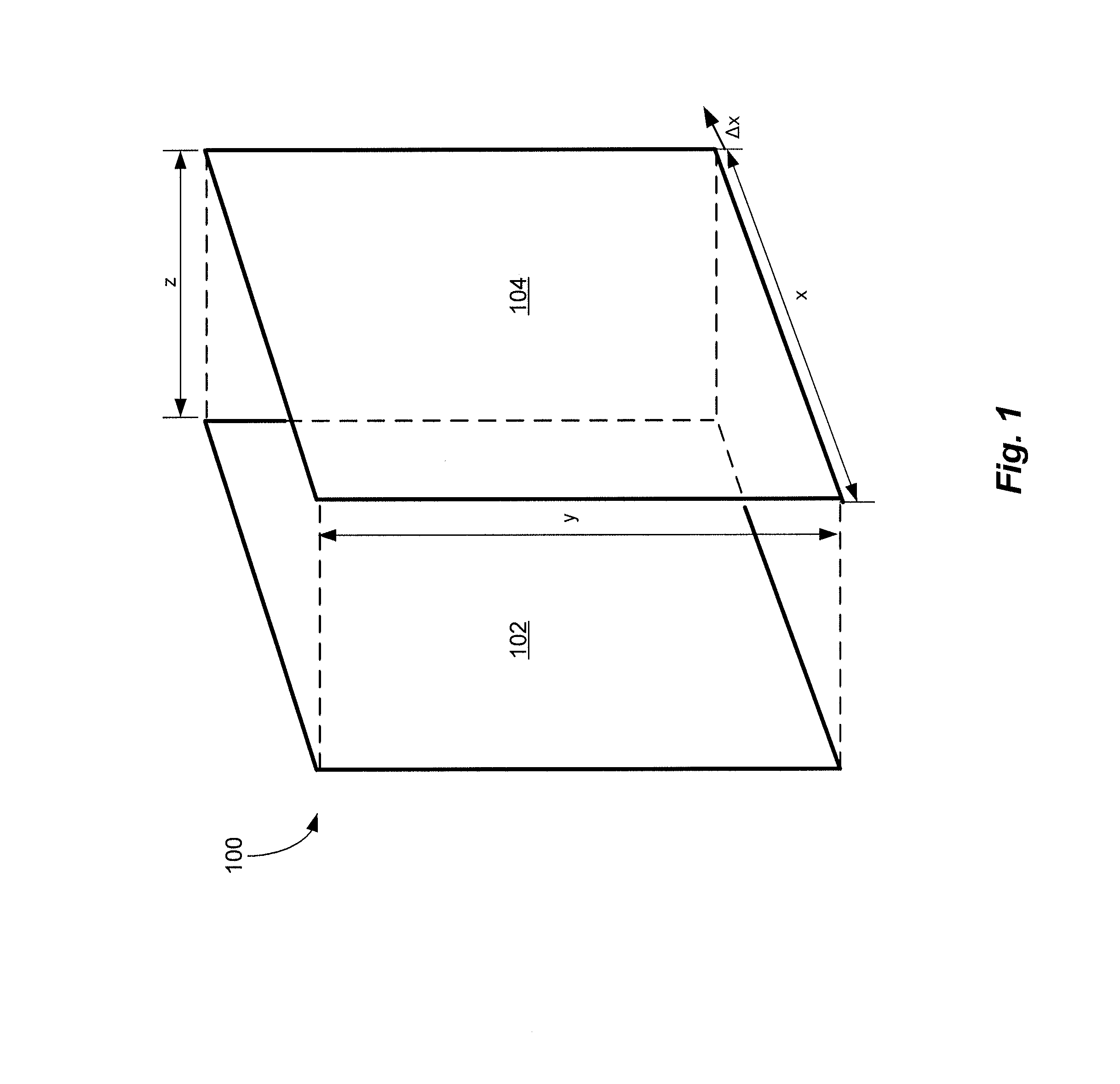
One drawback of the typical MEMS capacitive sensor employing variable-gap sensing is that the relationship between the change in the capacitance, ΔCz, of the variable, parallel-plate capacitors and the displacement of the proof mass is non-linear, as demonstrated by the term “z2” in the denominator of equation (2) above.
Moreover, the relative movement of the parallel plates of the respective parallel-plate capacitors can cause the dielectric material (e.g., the air) to rush into and / or out of the gap space between the parallel plates, resulting in a significant damping effect referred to herein as “squeeze-film damping”.

Method used


Image

  • Highly sensitive capacitive sensor and methods of manufacturing the same
  • Highly sensitive capacitive sensor and methods of manufacturing the same
  • Highly sensitive capacitive sensor and methods of manufacturing the same

Examples


Embodiment Construction

[0021]Micro-machined capacitive sensors implemented in micro-electro-mechanical system (MEMS) processes are disclosed that have high sensitivity, while providing a relatively large linear capacitive sensing range. In accordance with the disclosed micro-machined capacitive sensors, capacitive sensing is achieved via what is referred to herein as “variable-area sensing”, which employs a transduction mechanism in which the relationship between changes in the capacitance of variable, parallel-plate capacitors and displacements of a proof mass is generally linear. Each respective parallel-plate capacitor is formed by a finger / electrode pair, in which both the finger and the electrode have rectangular tooth profiles that include a number of substantially rectangular teeth. Because changes in an overlapping area of the parallel plates are multiplied by the number of rectangular teeth, while the standing capacity of the micro-machined capacitive sensor remains relatively high, the sensitivi...


PUM

PropertyMeasurementUnit
massaaaaaaaaaa
geometric shapeaaaaaaaaaa
capacitanceaaaaaaaaaa

Abstract

Micro-machined capacitive sensors implemented in micro-electro-mechanical system (MEMS) processes that have higher sensitivity, while providing an increased linear capacitive sensing range. Capacitive sensing is achieved via variable-area sensing, which employs a transduction mechanism in which the relationship between changes in the capacitance of variable, parallel-plate capacitors and displacements of a proof mass is generally linear. Each respective variable, parallel-plate capacitor is formed by a finger / electrode pair, in which both the finger and the electrode have rectangular tooth profiles that include a plurality of rectangular teeth. Because changes in the overlapping area of the finger and the electrode are multiplied by the number of rectangular teeth, while the standing capacity of the micro-machined capacitive sensor remains relatively high, the sensitivity of the micro-machined capacitive sensor employing variable-area sensing is significantly increased per unit area of the finger and the electrode.

Description

STATEMENT REGARDING FEDERALLY SPONSORED RESEARCH OR DEVELOPMENT[0001]Not applicableFIELD OF THE INVENTION[0002]The present application relates generally to micro-electro-mechanical systems (MEMS) and devices, and more specifically to micro-machined capacitive sensors and their implementations in MEMS processes.BACKGROUND OF THE INVENTION[0003]In recent years, micro-machined capacitive sensors have been increasingly employed for providing inertial sensing in an array of automotive and consumer electronics applications. A typical micro-machined capacitive sensor implemented in a micro-electro-mechanical system (MEMS) process (referred to herein as the “typical MEMS capacitive sensor”) includes a substrate, a proof mass, a plurality of spring beams tethering the proof mass to the substrate, a plurality of fingers extending from the proof mass, and a plurality of electrodes attached to the substrate having readout elements extending therefrom. In the typical MEMS capacitive sensor, the ...

Claims


Application Information

Patent Timeline
Patent Type & Authority Applications(United States)
IPC IPC(8): G01P15/125C23F1/00
CPCG01P2015/0814G01P15/125
Inventor ZHOU, HANQINJIANG, LEYUEVARGHESE, MATHEWLIU, HAIDONG
Owner MEMSIC
Learn More