
Solar panel racking assembly

Inactive Publication Date: 2012-03-01
DYNORAXX
View PDF21 Cites 62 Cited by
  • Summary
  • Abstract
  • Description
  • Claims
  • Application Information

AI Technical Summary

Benefits of technology

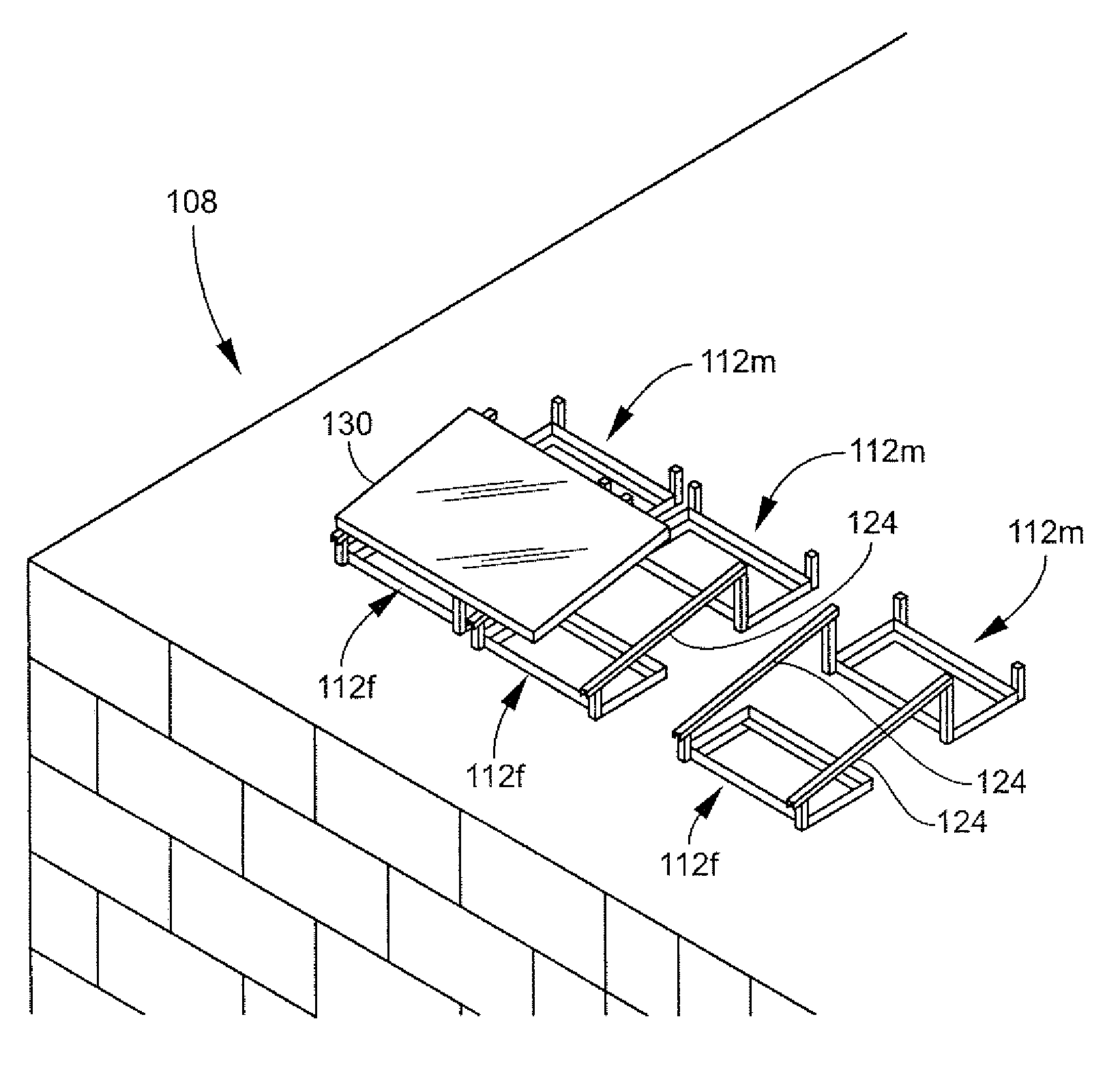
[0016]The present invention is a ballasted solar panel mounting system primarily for mounting solar panels to a flat roof. The mounting system reduces wasted space by positioning the first and / or the last row of bases beneath the panel. This potentially provides room for an additional row of panels and generation of a greater amount of electricity per square foot of area. Additionally, the mounting system uses bases with upwardly extending posts that are integrally connected to the bases that support ballasts. By integrally, it is meant that the two parts are permanently fastened together and require no additional fastening by the customer or user of the product. Such a permanent fastening system would include, a weld, rivet, nut and bolt, locking fastener, or other permanent fastening means.
[0017]Because the legs are integrally attached to the base, further assembly required is done at the top end of the legs where the need for bending is minimized. Moreover, the unique system for installing solar panels can be installed without a jig. In some instances, it can be installed with only a single reference line (e.g., chalk line). Additionally, the bases are configured to be stackable for inexpensive storage and distribution.
[0033]In another embodiment, the bottom surface comprises a tread surface that elevates the base and engages a floor surface. The tread surface resists slipping against the floor compared to a material from which the base is generally made. Generally, the base is made of steel including galvanized steel, stainless steel or steel that is coated with a paint coating such as powder coating paint.
[0053]In another embodiment, there is an apparatus for securing a solar panel to a support, the apparatus comprising a clamping bracket having a passage and a lip configured to receive a solar panel under the lip. A cam actuated clamping mechanism having a cam press on the first end of a cam bolt and a nut on the other end of the cam bolt, the cam actuated clamping mechanism rotates the cam press from a first position to a second position that biases the clamping bracket against to support to clamp a solar panel there between. In one embodiment, the cam press is actuated from the first position to the second position by moving a cam lever and wherein the support further comprises a lock slot into which the cam lever can be moved to prevent movement of the cam press from the second position.

Problems solved by technology

The cost of solar panel technology includes a significant investment in installation of the equipment.
The quality of installation also affects the efficiency of solar panel installation.
It should be understood that while generally flat, flat roofs are often uneven due to settling of the building, construction imperfections, etc.
Such a system is undesirable because roof penetration potentially causes leaks in the roof.
Thus multiple steps of assembly are required making installation of this unnecessarily time consuming to install.
The trough tends to trap moisture beneath the system and cause damming and pooling of rainwater.

Method used


Image

  • Solar panel racking assembly
  • Solar panel racking assembly
  • Solar panel racking assembly

Examples


Embodiment Construction

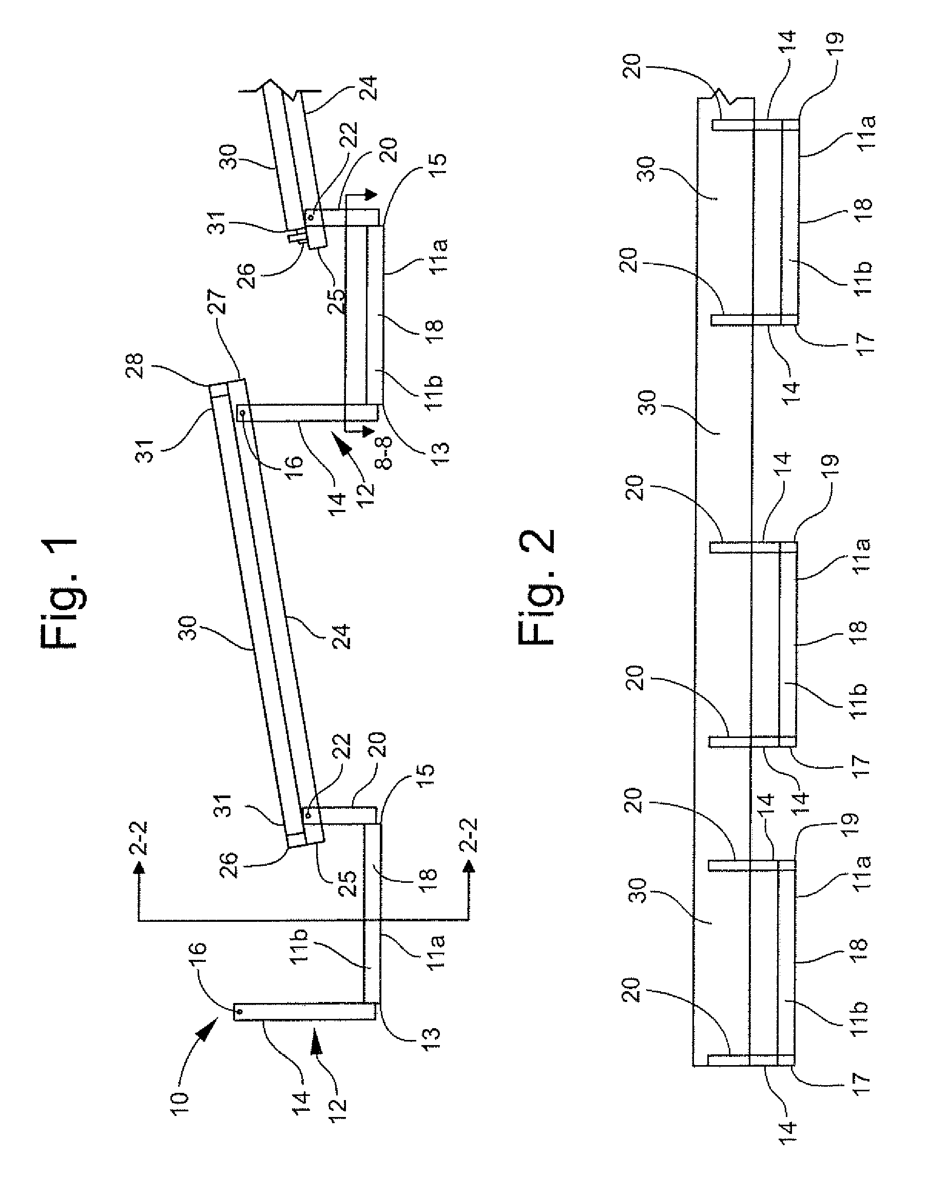
[0076]The present invention is a solar panel mounting system that is capable of being packaged for shipping in a compact and efficient manner. The assembly is more efficient requiring fewer steps, less bending and stooping on the part of the installer, and uses fastener systems that reduces or altogether eliminates the need for additional tools to install the racking system structure. The product is easy to install and can be installed without formal training by a layperson.

[0077]One example of the present invention is illustrated in FIG. 1 with reference to FIG. 2. The solar panel mounting system 10 comprises a plurality of base supports or bases 12 that are arranged to support a plurality of generally horizontal panel frames or support bars 24 or rails. The support bars 24 support a solar panel 30 that is affixed to the support bars 24 by panel clamps 26 and 28. The base supports 12 have a ballast tray 18 that is affixed to a pair of upwardly extending long arms or long posts 14 a...


PUM


Abstract

The present invention is a ballasted solar panel mounting system primarily for mounting solar panels to a roof. The mounting system reduces waste space by positioning the first and / or the last row of bases beneath the panel. This potentially provides room for an additional row of panels and generation of a greater amount of electricity per square foot of area. Additionally, the mounting system uses bases with upwardly extending posts that are integrally connected to the bases that support ballasts. Thus, all assemblies that require attaching one part of the system to another is done at an elevated level to reduce the amount of bending required by the installers. Moreover, the unique system for installing solar panels can be installed without a jig. In some instances, it can be installed with only a single reference line (e.g., chalk line). Additionally, the bases are configured to be stackable for inexpensive storage and distribution.

Description

CROSS-REFERENCE TO RELATED APPLICATIONS[0001]This application is a continuation-in-part of U.S. application Ser. No. 12 / 779,256 filed May 13, 2010 which claims the benefit of U.S. Provisional Application No. 61 / 178,029 filed May 13, 2009 both application are incorporated by reference in their entirety. This application also claims the benefit of U.S. Provisional Application No. 61 / 380,073 filed Sep. 3, 2010 which is incorporated by reference in its entirety.BACKGROUND OF THE INVENTION[0002]1. Field of Invention[0003]This invention relates generally to systems for mounting solar panels or photovoltaic cells and more specifically to ballasted roof mounted racking systems for mounting photovoltaic cells.[0004]2. Discussion of Related Art[0005]Solar energy provides the opportunity to generate electricity without consumption of fossil fuels and is considered clean technology. In recent years, the development of technology for solar thermal systems and photovoltaic systems has improved th...

Claims


Application Information

Patent Timeline
IPC IPC(8): H01L31/048F24J2/52
CPCF24J2/5239F24J2/5256F24J2002/5279H02S20/24Y02B10/12Y02E10/47Y02B10/20F24J2002/5292F24S2025/013F24S25/16F24S2025/02F24S25/634Y02E10/50Y02B10/10
Inventor RIZZO, NATHAN
Owner DYNORAXX
Learn More