LED light bulb

a technology of led light bulbs and diodes, which is applied in the direction of cathode-ray/electron beam tube circuit elements, lighting and heating apparatus, semiconductor devices for light sources, etc. it can solve the problems of leds and glass lampshades being overheated after long use, waste heat still accumulating continuously on the heat sink, etc., to achieve rapid heat conductivity, improve cooling effect, and increase cooling area

Inactive Publication Date: 2012-03-01
CHUANG SHENG YI
View PDF2 Cites 46 Cited by
  • Summary
  • Abstract
  • Description
  • Claims
  • Application Information

AI Technical Summary

Benefits of technology

[0008]The structure thus formed can conduct heat of the LED circuit boards to the heat conductive post which further conducts the heat to the heat sink. The heat sink is exposed outside the lampshade and has a greater cooling area in contact with air, hence can quickly conduct the heat from the interior of the lampshade outside. Moreover, with the current of the LED circuit boards is converged on the first and second current converged boards and is connected with the electric connection structure through the first and second conductive wires, the current does not pass through the heat conductive post and heat sink, therefore the heat sink can be exposed outside the lampshade in contact with the air directly, an improved cooling effect can be accomplished.

Problems solved by technology

In the event that the flowing speed of the airflow is not fast enough or air temperature is higher, waste heat will still be accumulated continuously on the heat sink.
Moreover, flowing of the airflow inside the glass lampshade is difficult, the LEDs and glass lampshade could be overheated after used for a long time.

Method used


Image

  • LED light bulb
  • LED light bulb
  • LED light bulb

Examples


Embodiment Construction

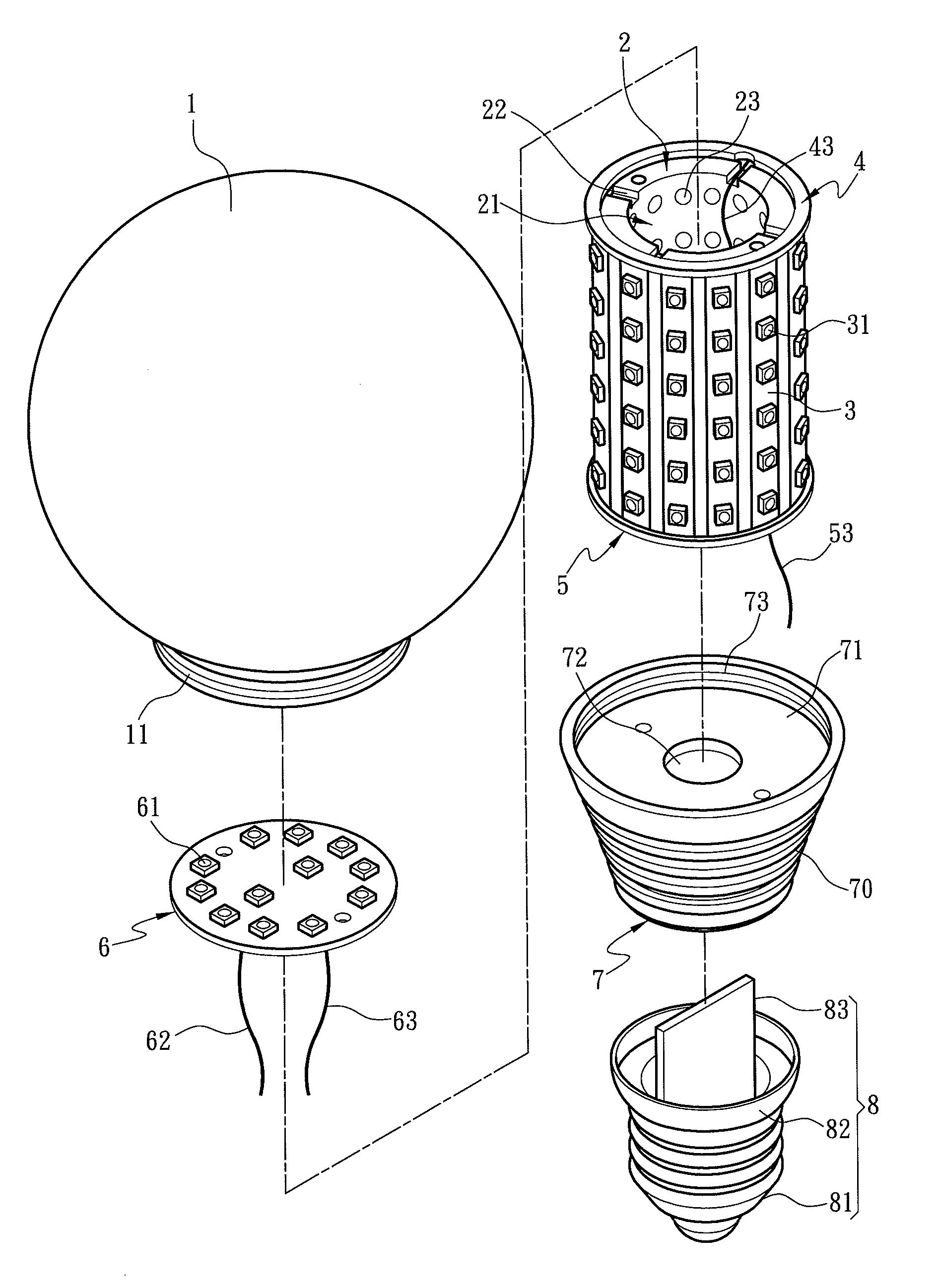
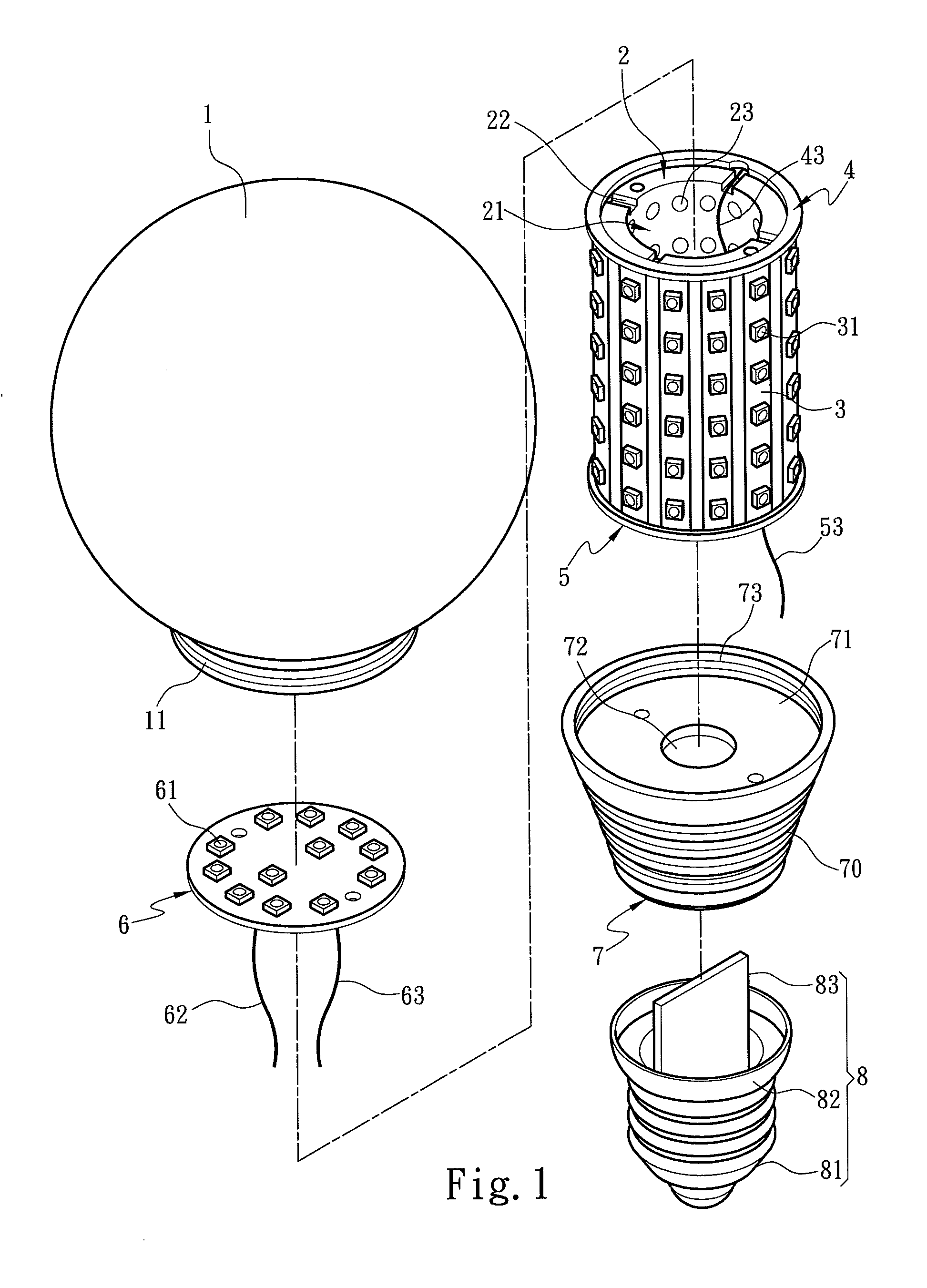
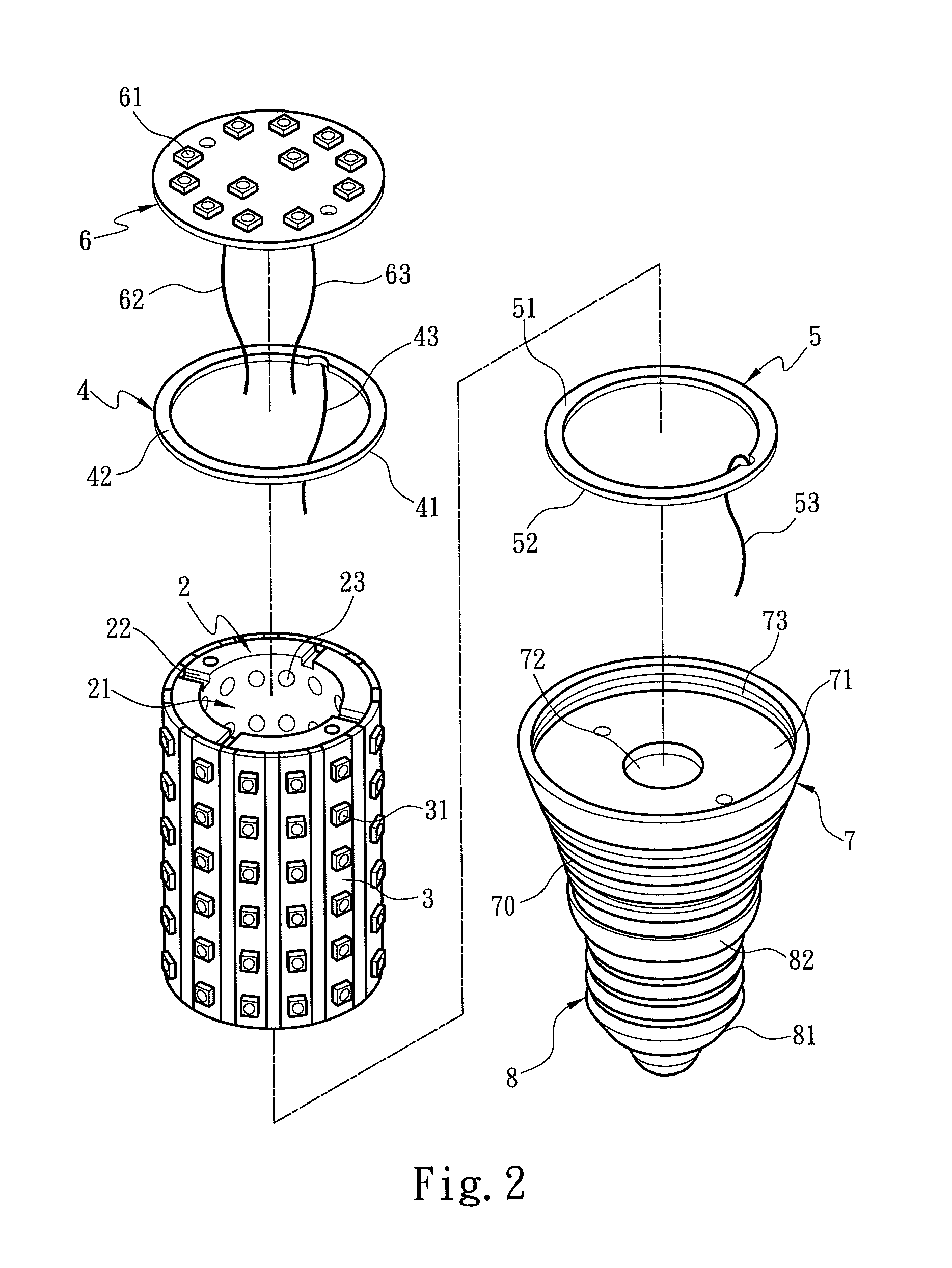
[0013]The present invention aims to provide an LED light bulb. Referring to FIGS. 1 and 2, the LED light bulb includes a heat conductive post 2 coupled with a plurality of LED circuit boards 3. The heat conductive post 2 is a hollow post and has a through hole 21 inside with an inner wall formed with a plurality of cavities 23 to increase air contact area. The LED circuit boards 3 are connected with each other and surround the periphery of the heat conducive post 2. Each LED circuit board 3 has a plurality of LEDs 31 coupled in series. With the LED circuit boards 3 surrounding the periphery of the heat conductive post 2, light generated by the LEDs 31 can project in multiple directions for surrounding illumination effect. The LED circuit board 3 has a first electrode end and a second electrode end formed at an upper and a lower end thereof connected respectively to a high voltage end and a low voltage end of a DC power to conduct the DC power to drive the LEDs 31 to emit light. To c...


PUM


Abstract

An LED light bulb includes a heat conductive post coupled with a plurality of LED circuit boards. The LED circuit boards are electrically connected to a first current converged board and a second current converged board. The first and second current converged boards also are connected respectively to a first conductive wire and a second conductive wire to converge current of the LED circuit boards. The heat conductive post further is connected to a heat sink which has a wiring aperture threaded through by the first and second conductive wires and a coupling portion coupled with a lampshade. The invention also includes an electric connection structure coupled with the heat sink in an insulation manner. The electric connection structure is electrically connected to the first and second conductive wires and connected to a power source to supply electric power through the first and second conductive wires.

Description

FIELD OF THE INVENTION[0001]The present invention relates to an LED (light emitting diode) light bulb and particularly to an LED light bulb equipped with an exposed heat sink and a circuit board to converge current to prevent the heat sink from receiving the current.BACKGROUND OF THE INVENTION[0002]LED provides many advantages such as longer lifespan, less electric power consumption, greater brightness and utilizing eco-friendly materials. With advance of LED fabrication processes and cost reduction, applications of LED become increasingly popular, asides from used on traffic lights or indication lights on electric appliances, they also are adopted on lighting fixtures for environment decoration and illumination. To make the LEDs to be applied to the ordinary light bulbs, a technique has been developed to couple the LEDs with a casing of the conventional light bulb.[0003]For instance, R.O.C. patent No. M358247 entitled “LED lamp adaptable to varying sockets” discloses “an LED lamp a...

Claims


Application Information

Patent Timeline
Patent Type & Authority Applications(United States)
IPC IPC(8): H01K1/62
CPCF21K9/135F21Y2101/02F21V29/83F21V3/00F21Y2111/005F21V23/002F21K9/232F21Y2107/30F21Y2115/10
Inventor CHUANG, SHENG-YI
Owner CHUANG SHENG YI
Why Eureka
Try Eureka