Dc-dc converter and semiconductor device

a technology of dc-dc converter and semiconductor device, which is applied in the direction of dc-dc conversion, power conversion system, instruments, etc., can solve the problems of complex configuration of controller and use as controller of inverter, and achieve the effect of simple configuration and simple configuration

Active Publication Date: 2012-03-01
SEMICON ENERGY LAB CO LTD
View PDF5 Cites 12 Cited by
  • Summary
  • Abstract
  • Description
  • Claims
  • Application Information

AI Technical Summary

Benefits of technology

[0022]An embodiment of the present invention can provide a DC-DC converter that includes a control circuit and has a simple configuration

Problems solved by technology

In the case where the feedback voltage which is a negative voltage is converted into a positive voltage in a controller in this manner, the configuration of the controller becomes complex.
Further, as illustrated in FIG. 6, when the

Method used


Image

  • Dc-dc converter and semiconductor device
  • Dc-dc converter and semiconductor device
  • Dc-dc converter and semiconductor device

Examples


embodiment 1

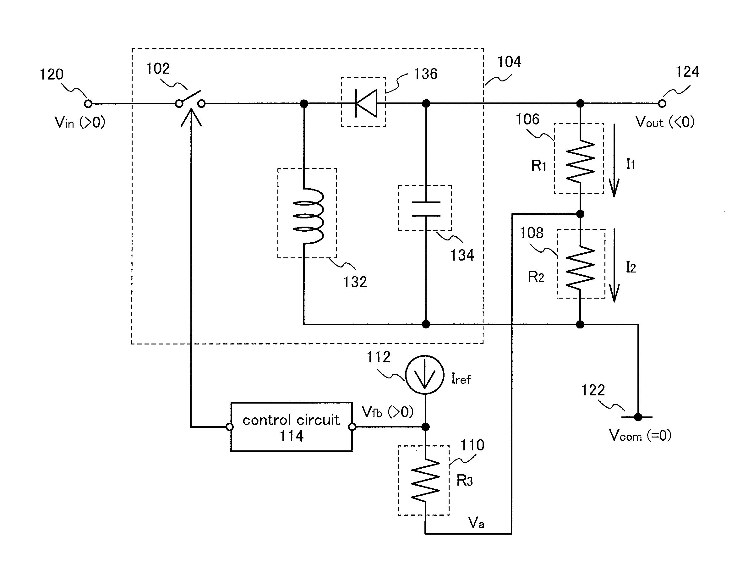
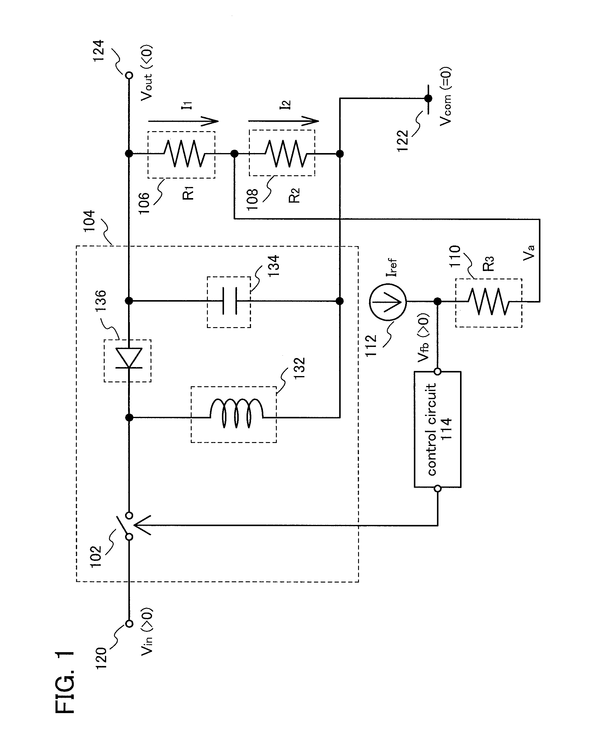
[0044]In this embodiment, an example of the configuration of a DC-DC converter will be described with reference to FIG. 1. FIG. 1 illustrates the configuration of an inverting DC-DC converter as an example of a DC-DC converter.

[0045]In FIG. 1, a DC-DC converter includes a power conversion portion 104, a resistor 106 (hereinafter, referred to as a first resistor), a resistor 108 (hereinafter, referred to as a second resistor), a resistor 110 (hereinafter, referred to as a third resistor), a constant current supply 112, and a control circuit 114.

[0046]The power conversion portion 104 includes a switching element 102, a coil 132, a capacitor 134, and a diode 136.

[0047]A first terminal of the switching element 102 is connected to an input terminal 120, and a second terminal of the switching element 102 is connected to a cathode of the diode 136. The switching element 102 controls connection between the input terminal 120 and the cathode of the diode 136. Specifically, an input voltage V...

embodiment 2

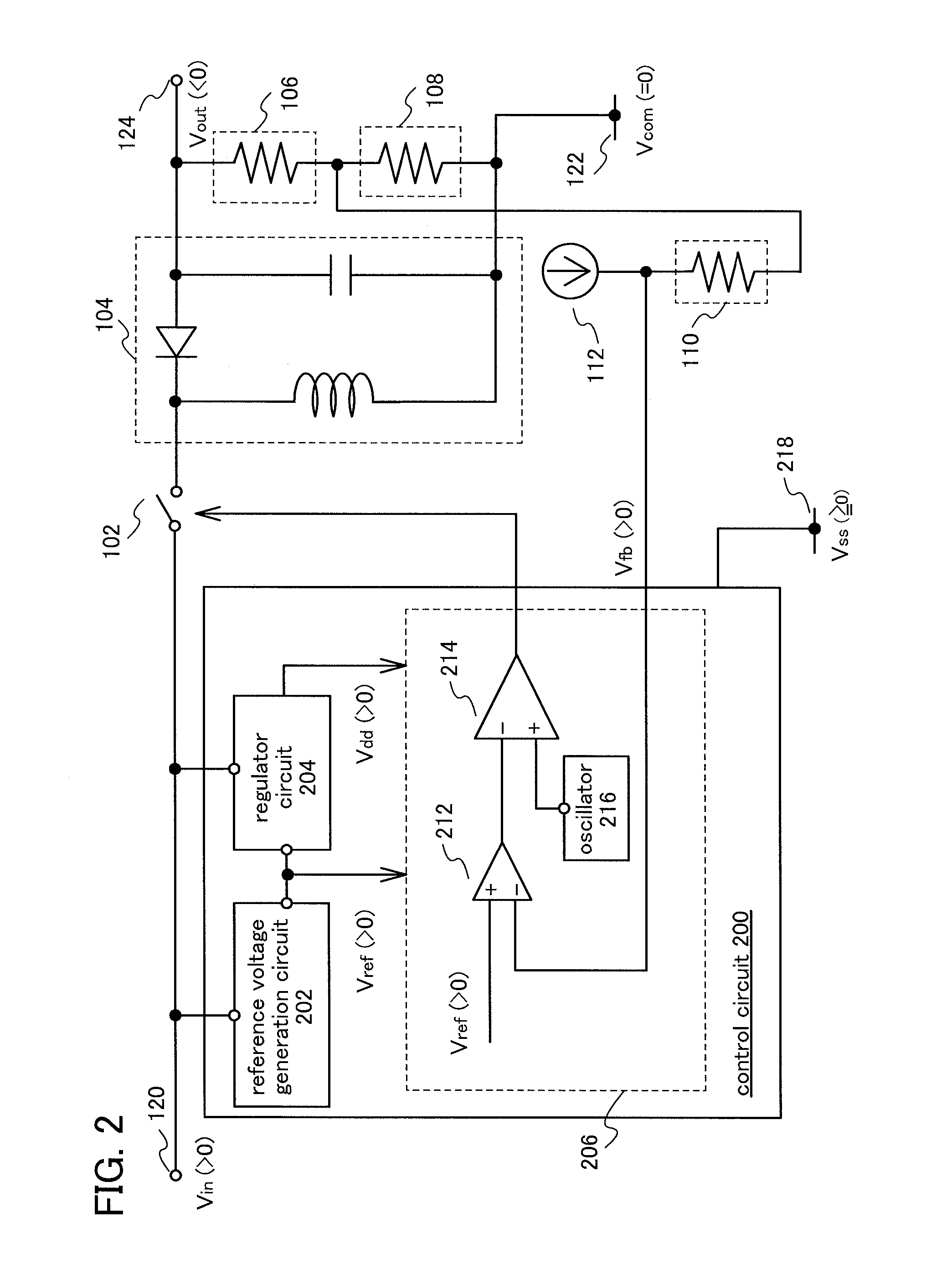
[0068]In this embodiment, an example of the configuration of a control circuit included in a DC-DC converter will be described with reference to FIG. 2.

[0069]In FIG. 2, a control circuit 200 includes a reference voltage generation circuit 202, a regulator circuit 204, and a control signal generation portion 206. The control circuit 200 in FIG. 2 corresponds to the control circuit 114 in FIG. 1.

[0070]The control circuit 200 is connected to a terminal 218. A low power supply voltage Vss is supplied from the terminal 218. The control circuit 200 operates with a voltage between the input voltage Vin and the low power supply voltage Vss. Here, the low power supply voltage Vss satisfies Vssdd with respect to a high power supply voltage Vdd. Note that the low power supply voltage Vss, may be set at the reference potential Vcom. In the following description, Vss is 0 V.

[0071]The reference voltage generation circuit 202 has a function of generating the reference potential Vref. Here, in the ...

embodiment 3

[0079]In this embodiment, an example of the configuration of a circuit which generates the reference current Iref and which is provided in a DC-DC converter will be described.

[0080]In FIG. 1 described in Embodiment 1, the control circuit 114 and the constant current supply 112 that generates the reference current Iref are separately provided. On the other hand, a circuit which generates the reference current Iref can be provided in the control circuit 114, instead of the constant current supply 112.

[0081]In this embodiment, an example of the configuration of a circuit which generates the reference current Iref and which is provided in the control circuit 114 will be described with reference to FIG. 3.

[0082]FIG. 3 illustrates an example of the configuration of the circuit that generates the reference current Iref (hereinafter, referred to as a reference current generation circuit). The reference current generation circuit includes a reference voltage generation circuit 302, an amplif...


PUM


Abstract

A DC-DC converter includes a power conversion portion including a switching element; a first resistor having one terminal electrically connected to the power conversion portion; a second resistor having one terminal electrically connected to the other terminal of the first resistor; a third resistor having one terminal electrically connected to the other terminal of the first resistor; a constant current supply electrically connected to the other terminal of the third resistor; and a control circuit electrically connected to the other terminal of the third resistor and configured to control the switching element. Resistance R1 of the first resistor, resistance R2 of the second resistor, resistance R3 of the third resistor, a reference current Iref output from the constant current supply, and an output voltage Vout output from the power conversion portion satisfy a following formula:
{(1+R3R2)·R1+R3}·Iref>-Vout.

Description

TECHNICAL FIELD[0001]The technical field relates to a DC-DC converter and a semiconductor device.BACKGROUND ART[0002]Various electronic devices, electric propulsion vehicles, and the like include DC-DC converters (also referred to as DC converter circuits or DC to DC power supplies) that convert a direct current power to another direct current power. For example, DC-DC converters are utilized for generating a constant output voltage or a plurality of output voltages with different values on the basis of voltage with large fluctuation.[0003]As an example of the configuration of a DC-DC converter, Patent Document 1 discloses a non-isolated DC-DC converter including a coil, a diode, and a transistor.[0004]There are various kinds of non-isolated DC-DC converters such as a step-up DC-DC converter, a step-down DC-DC converter, an inverting DC-DC converter, and a step-up and step-down DC-DC converter.[0005]Step-up DC-DC converters convert an inputted direct-current voltage into a direct-cu...

Claims


Application Information

Patent Timeline
IPC IPC(8): G05F1/00
CPCH02M3/158H02M3/005H02M3/156H02M1/0093
Inventor WATANABE, KAZUNORI
Owner SEMICON ENERGY LAB CO LTD
Why Eureka
Try Eureka