Method and Apparatus for Anti-Biofouling of Optics in Liquid Environments

a liquid environment and optics technology, applied in the field of optics, can solve the problems of not being suitable for coating optics windows, reducing the quality of images generated by underwater optical systems, and affecting the effect of environment, so as to prevent the biofouling of underwater optical systems

Inactive Publication Date: 2012-03-01
RAYTHEON CO
View PDF12 Cites 70 Cited by
  • Summary
  • Abstract
  • Description
  • Claims
  • Application Information

AI Technical Summary

Benefits of technology

[0013]The present invention provides an apparatus and a method to prevent biofouling of underwater optical systems, within and as part of the underwater optical systems, without removing the optical systems from the water and without disbursement of chemicals into the water.

Problems solved by technology

Biofouling of the optics window can greatly reduce the quality of images generated by the underwater optical system.
However, anti-biofouling coatings tend to be opaque to the transmission of light, and therefore, tend not to be suitable to coat an optics window.
Therefore, in general, underwater optical systems must be removed from the water for cleaning of the optic optics window from time to time, and too often in the case of some underwater optical systems.
Although the effects of such chemical systems are temporary, only lasting a few months, the effect on the environment is larger than desired for an anti-biofouling system.
Furthermore the chemical release mechanisms are subjected to the ocean environment, e.g., pressure, resulting in reduced reliability.
Ultraviolet light in a UVA band (about 320-400 nm) can cause skin damage and may cause melanomatous (skin cancer).
Ultraviolet light in a UVC band (below about 280 nm) is the strongest, having the greatest energy per photon (eV), and is potentially the most harmful form.

Method used


Image

  • Method and Apparatus for Anti-Biofouling of Optics in Liquid Environments
  • Method and Apparatus for Anti-Biofouling of Optics in Liquid Environments
  • Method and Apparatus for Anti-Biofouling of Optics in Liquid Environments

Examples


Embodiment Construction

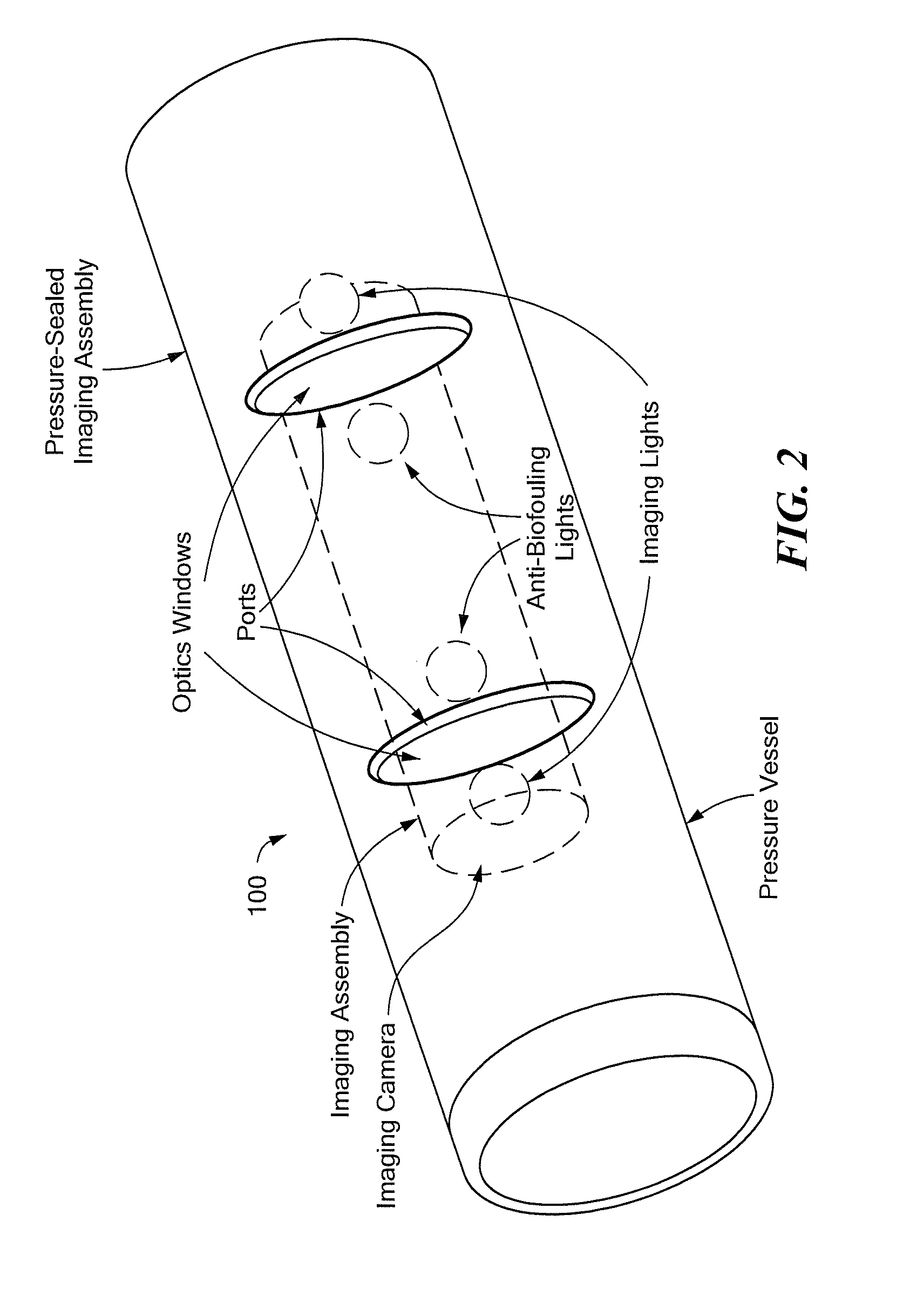
[0027]Before describing the present invention, some introductory concepts and terminology are explained. As used herein, the term “optical system” is used to describe any system capable of generating an optical image upon any medium, including, but not limited to, film, paper, and digital media. An optical system can include a variety of components, for example, a radio transmitter and / or a computer. As used herein, the term “imaging assembly” is used to describe an image-generating portion of an optical system, including an “imaging camera” and light sources. As used herein, the term “pressure-sealed imaging assembly” is used to describe an imaging assembly disposed in and including a pressure vessel. A pressure-sealed imaging assembly can be a part of an optical system.

[0028]It should be noted that reference is sometimes made herein to assemblies having a particular shape (e.g., cylindrical). One of ordinary skill in the art will appreciate, however, that the techniques described ...


PUM


Abstract

The present invention provides an apparatus and a method to prevent biofouling of underwater optical systems using ultraviolet light generated from within a pressure vessel and through an optics window, without removing the optical systems from the water and without disbursement of chemicals into the water.

Description

FIELD OF THE INVENTION[0001]This invention relates generally to optical apparatus and, more particularly, to an apparatus, system, and method for keeping free of biological fouling an optical system immersed in a liquid, for example, the ocean.BACKGROUND OF THE INVENTION[0002]There is a desire for optical sensors that can be used in liquids, for example, in the ocean, for long periods of time. Underwater objects, particularly underwater objects that are in the water for long periods of time, have external surfaces that are subject to so-called “biofouling.” A used herein, the term “biofouling” is used to describe an attachment of organisms that live in the liquid, e.g., in the ocean, to surfaces, particularly to man-made surfaces. The organisms can be small, for example, algae, or larger, for example, barnacles.[0003]Detrimental effects of biofouling to man-made surfaces are well known and wide-ranging. Underwater optical systems have an optics window though which light must pass in...

Claims


Application Information

Patent Timeline
Patent Type & Authority Applications(United States)
IPC IPC(8): H04N7/18G21G5/00
CPCB63C11/48C02F1/32G02B23/22B63B59/08C02F2303/20B63B59/04G02B27/0006
Inventor THOREN, MATTHEW D.PIPER, ANDREW M.
Owner RAYTHEON CO
Why Eureka
Try Eureka