Method of synchronization, corresponding system and device

a synchronization and corresponding system technology, applied in the field of information and communication technology, can solve the problems of insufficient synchronization of slave clocks, weak jitter of slave clocks, and inability to receive dedicated cables, so as to save bandwidth, simplify implementation, and find visual comfor

Inactive Publication Date: 2012-03-01
CANON KK
View PDF3 Cites 30 Cited by
  • Summary
  • Abstract
  • Description
  • Claims
  • Application Information

AI Technical Summary

Benefits of technology

[0050]This periodicity ensures tracking of the changes in the own clocks of each device (for example depending on temperature). Thus, the effectiveness of the invention may be maintained by periodically updating the reference or target frame rate using that monitoring. Complex mechanisms for managing drift and compensation may thus be avoided.
[0051]In an embodiment of the invention, the adapting of the source video stream comprises duplicating at least one image in order for the video stream to attain said target frame rate.
[0052]This provision, implementing image duplication, enables the integrity of the data to be maintained since there is no deletion of information. The visual comfort (on display of the video stream) is found to be improved.
[0053]Furthermore, the manipulation by entire image according to the invention proves to be of simpler implementation, at the network devices, than a manipulation by pixel or line.
[0054]In particular, the duplicating comprises a step of computing a drift between the source frame rate and the target frame rate, and the number of images to duplicate is a function of the computed drift to attain the target frame rate.
[0055]In an embodiment of the invention, the adapting of the source video stream is carried out by each receiving device receiving a source video stream that has a source frame rate less than the target frame rate.

Problems solved by technology

Without these synchronization means, the reception buffer memories of the recipient apparatuses would empty or fill up completely depending on whether the local frame rate is higher or lower than the source frame rate, so causing visual artefacts which for example take the form of an interruption of the video.
Furthermore, most of the apparatuses for the general public are not equipped to receive such a dedicated cable.
If it is fast, the slave clock may undergo strong jitter, that is to say a temporal irregularity, which may have consequences on the processing of the transported data.
Furthermore, the number of PLLs available in the hardware components is limited, and it is therefore necessary to use them judiciously.
Such a system therefore does not withstand variations in different display speeds between two display devices.
However, such an apparatus, reserved for high end professional use, has drawbacks with regard to its very high cost, and with regard to the technical and practical limitations of a resulting centralized system.
This is because all the video sources must be connected to that central apparatus, which may prove incompatible with a utilization requiring certain video sources to be spaced more or less far away, preventing the use of cables, such as for example a set of several cameras performing extended capture for a single homogenous display in real time.
This solution is not satisfactory in the presence of recipient apparatuses not sharing an image clock.
Furthermore, the solution proposed in that prior art document implements an addition of pixels which proves to be poorly tolerated by certain recipient apparatuses.
Moreover, in a multi-source system of the type previously referred to, the switching between two sources poses the additional problem of the synchronization relative to a reference source.
This change of reference clock requires progressive (and thus slow) processing operations at the synchronization means of the recipient apparatus which are used to follow the source clock.
To be precise, while the clock of the destination is not set to that of the source, the display is liable to be perturbed: a black screen is liable to appear until the destination clock has been re-synchronized.

Method used


Image

  • Method of synchronization, corresponding system and device
  • Method of synchronization, corresponding system and device
  • Method of synchronization, corresponding system and device

Examples


Embodiment Construction

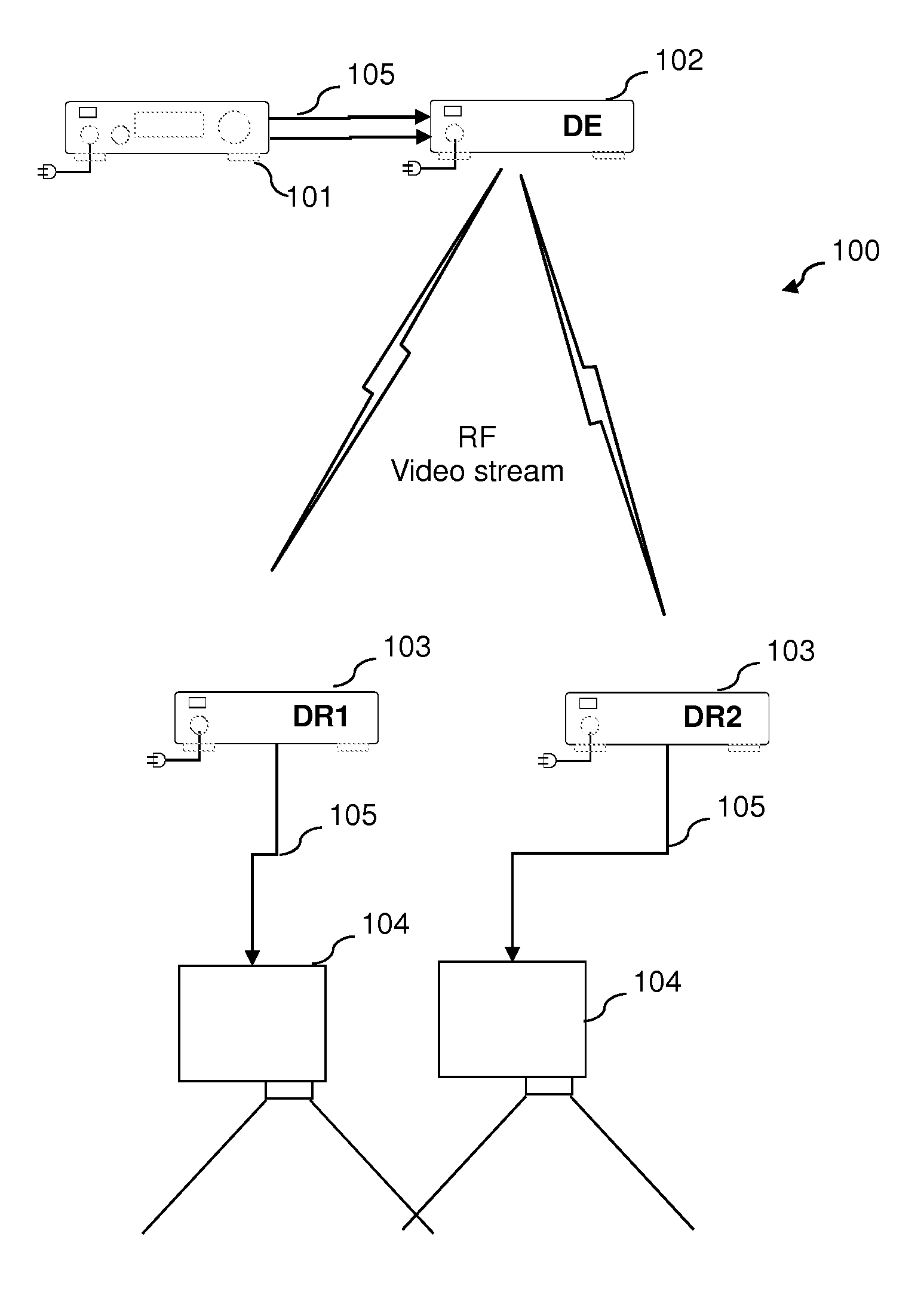
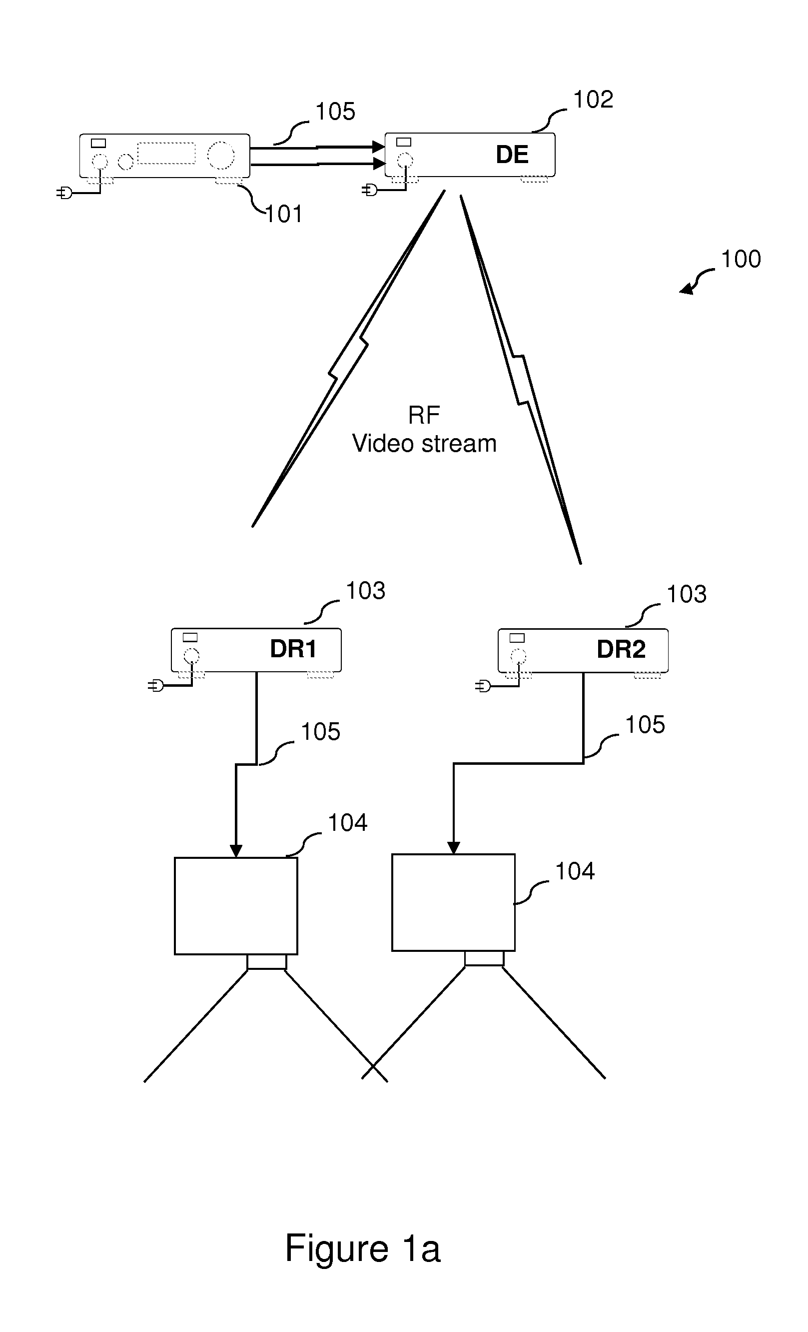
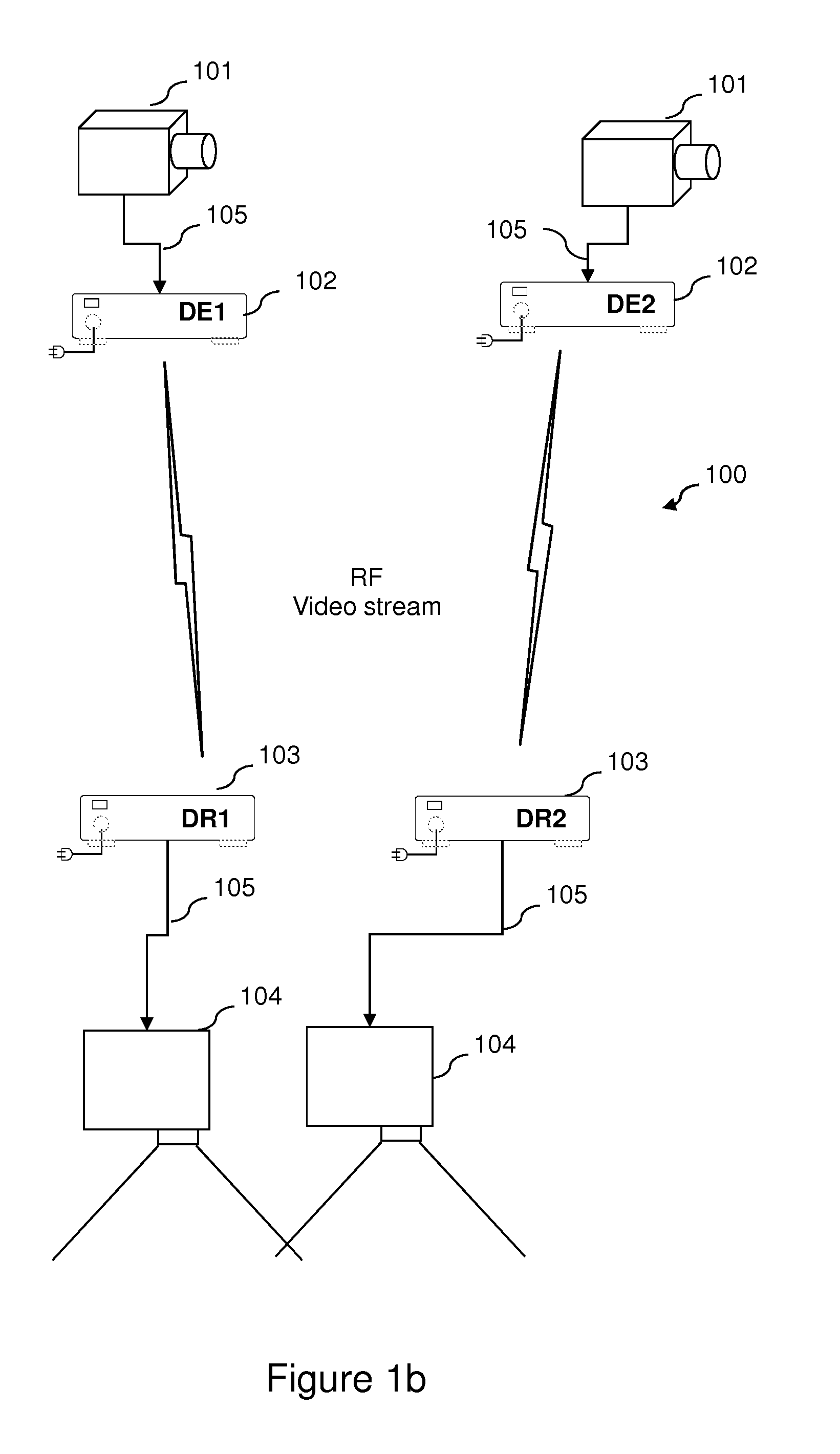
[0117]FIGS. 1a to 1c present various non-illustrative contexts in which the invention may be applied, in particular for the purposes of supplying a common cadence, or target frame rate denoted FlmTarget below, to all the devices of a distribution system for distributing video stream. The use of such a common cadence makes it possible to avoid re-synchronization of the devices in case of switching, for a receiving device, between sending devices or nodes linked to sources or, for a sending device, between receiving devices or nodes provided for the display of the video stream.

[0118]FIG. 1a presents a first scenario of use of a wireless multi-projection system 100. The system 100 comprises in particular a centralized video source 101 able to supply several video outputs simultaneously (PC video server for example of which the two source outputs are not synchronized). The video source 101 is connected to a sending device (DE) or sending node 102 (the network nodes connected to one or m...


PUM


Abstract

The present invention concerns a method of synchronization between devices of a distribution system for distributing video streams of images.The system comprises at least three devices, including a sender and a receiver, wherein a sending device is configured to receive, from a source, a video stream presenting a source image frequency, and a receiving device is configured to control the display, at a display frame rate, of a video stream on a display device.The method comprises obtaining a common target frame rate; adapting, by the devices, a source video stream received from a source, respectively, directly or via a sending device, from the source frame rate to the target frame rate; and adjusting, on each receiver, the display frame rate so as to control a display at said target frame rate.

Description

[0001]This application claims priority from French patent application No. 10 56914 of Aug. 31, 2010 which is incorporated herein by reference.FIELD OF THE INVENTION[0002]The present invention concerns a method of synchronization between devices of a distribution system for distributing video streams of images.[0003]The present invention generally concerns the field of information and communication technology.BACKGROUND OF THE INVENTION[0004]The present invention applies in particular to high-end video display systems with multiple projection. These are audio-visual projection systems constituted by several high definition audio-visual sources adapted to be displayed via one or more projectors or screens. These systems enable the implementation of video display systems of very large size and of very high quality, for example in the open air in a stadium for a sports event or a concert, or in a conference hall.[0005]These multiple projection video systems may also be used for simulato...

Claims


Application Information

Patent Timeline
Patent Type & Authority Applications(United States)
IPC IPC(8): H04N9/475
CPCG06F3/1438G06F3/1446G09G5/005H04N9/475G09G2340/0435H04N5/04G09G5/12
Inventor HALNA DU FRETAY, TRISTANEL KOLLI, YACINE SMAILFROUIN, LAURENT
Owner CANON KK
Why Eureka
Try Eureka