Antimicrobial ultraviolet light system for refrigerator sanitation

a technology for ultraviolet light and refrigerators, applied in domestic cooling devices, lighting and heating devices, furnaces, etc., can solve problems such as inability to detect malfunctions of users, and achieve the effects of convenient installation and use, sufficient coverage, and free of germs

Active Publication Date: 2012-03-01
JOHNSON EDWARD
View PDF3 Cites 40 Cited by
  • Summary
  • Abstract
  • Description
  • Claims
  • Application Information

AI Technical Summary

Benefits of technology

[0011]The present invention overcomes the limitations and disadvantages present in the art by providing a UV light system which is readily adaptable for installation and use with virtually any conventional refrigerator to aid in maintaining the refrigerator substantially free of germs, bacteria, and the like without the use of harmful chemicals. In accordance with the present invention a plurality of elongate UV light bars are provided, including a first stage light system electrically connected to a control box having a power cord. Additional UV light bars may be used and electrically connected in series (i.e. daisy chain fashion) with the first stage light system to provide sufficient coverage for virtually any size refrigerator.
[0013]As noted above, the first stage UV light system includes a control box and power cable. A significant aspect of the present invention involves use of a thin ribbon-wire power cable that provides power to the control box from an external electrical outlet. In accordance with a preferred embodiment, the power cable is fabricated from a thin ribbon wire which is intended to pass through the refrigerator sealing door gasket without significantly affecting the peripheral seal which prevents cold air from escaping from the interior of the refrigerator so as to allow the system to receive power from a conventional electrical outlet. The control box, includes a white incandescent light sensor, a variable timer knob, and a fault indicator light. The white incandescent light sensor senses when the refrigerator door is opened. Once the door closes, the sensor triggers the UV light to illuminate for a specified period of time. If the door is reopened while the UV light is illuminating the compartment, the sensor will temporarily turn off the UV light and reset itself to cycle again once the door is closed. The timer may be adjusted to meet the needs of the user by allowing for adjustment of desired UV activation (e.g. illumination “on” time”). A fault indicator light illuminates when the UV light is illuminated. Should the incandescent sensor fail to interrupt the UV light cycle, the indicator light will alert the user that there may be a system malfunction. The fault indicator feature is significant since UV light is not within the spectrum of light that is visible to the human eye. Thus, the user would not be able to detect a malfunction wherein the sensor fails to deactivate the UV light source(s).
[0016]Another object of the present invention is to provide an easy-to-install and economically practical method for reducing the spoliation of foodstuffs while stored in a refrigerator.
[0017]Yet another object of the present invention is to provide an independent power connection for the apparatus such that the seal of the refrigerator door is not compromised by ambient airflow into the compartment.

Problems solved by technology

Should the incandescent sensor fail to interrupt the UV light cycle, the indicator light will alert the user that there may be a system malfunction.
Thus, the user would not be able to detect a malfunction wherein the sensor fails to deactivate the UV light source(s).

Method used


Image

  • Antimicrobial ultraviolet light system for refrigerator sanitation
  • Antimicrobial ultraviolet light system for refrigerator sanitation
  • Antimicrobial ultraviolet light system for refrigerator sanitation

Examples


Embodiment Construction

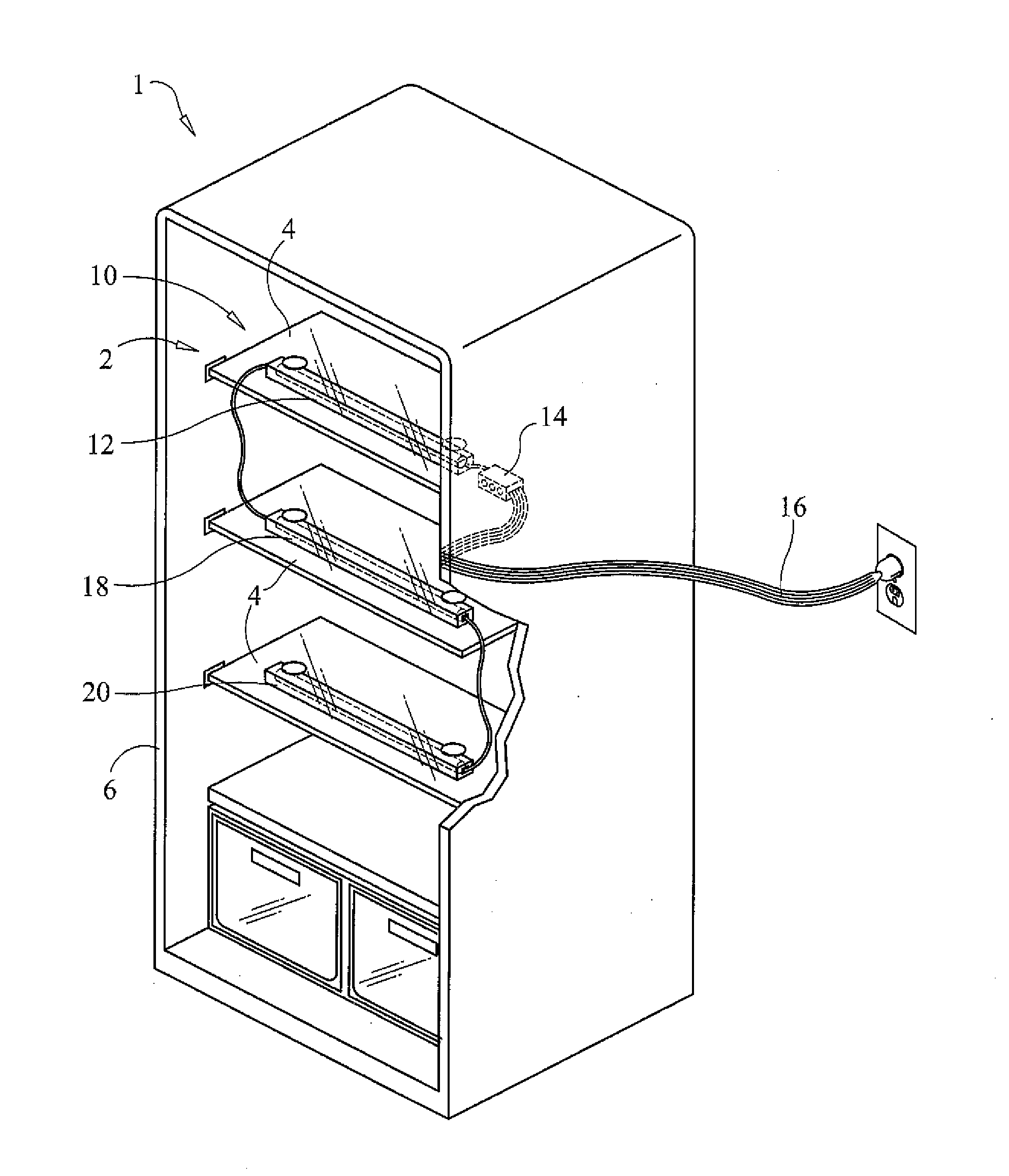
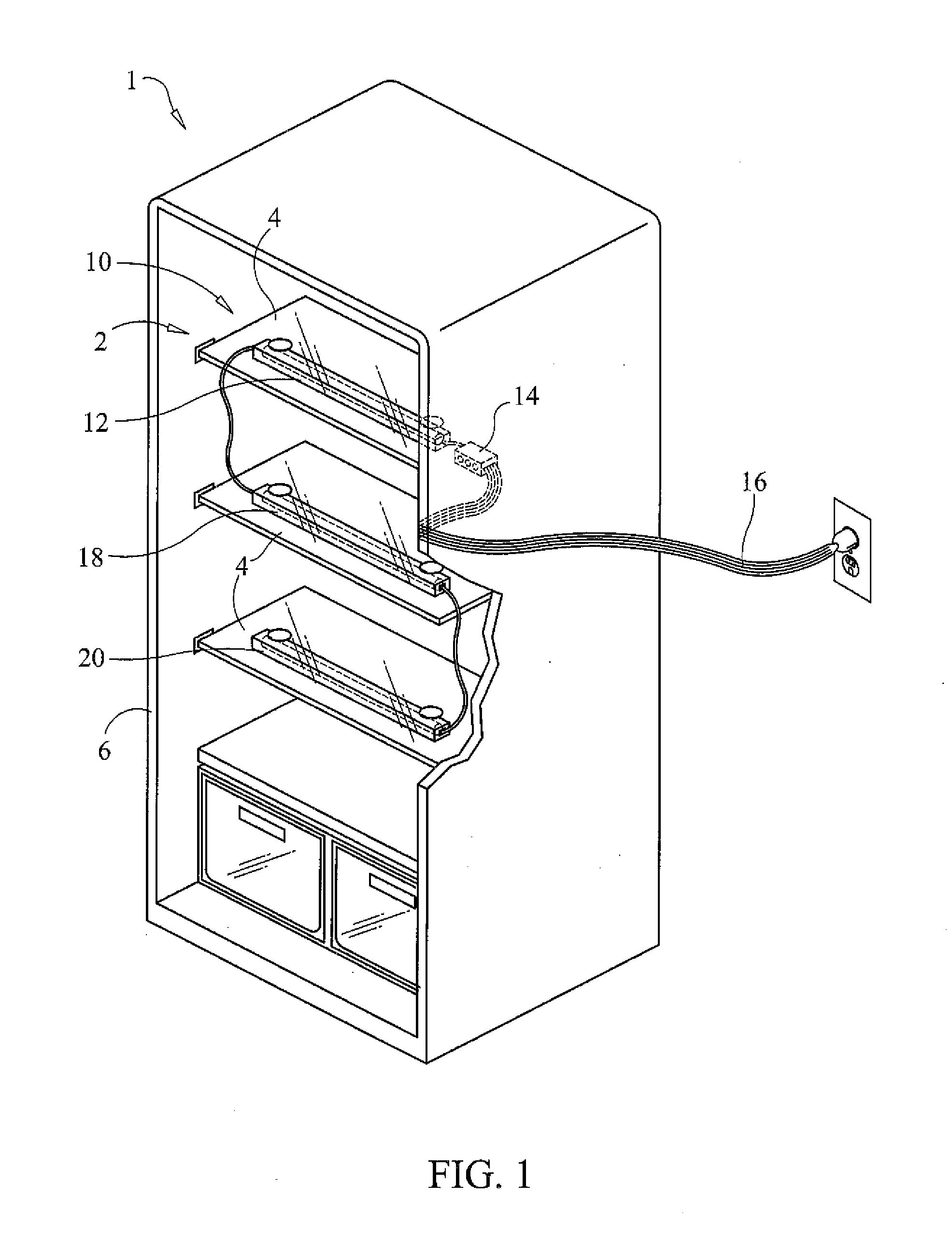
[0025]With reference now to the drawings, FIGS. 1-6 depict a preferred embodiment of a refrigerator UV light system, generally referenced as 10, that overcomes the limitations and disadvantages present in the art in accordance with the present invention. A food storage refrigerator, generally referenced as 1, defines an internal compartment 2 bounded by an opening and containing at least one shelf 4, the refrigerator further includes a door 5 configurable between a closed configuration and a closed configuration and a gasket 6, wherein the gasket forms a thermal seal between the refrigerator and the door when the door is in the closed configuration. Gasket 6 may be affixed to the door, or to the refrigerator main body. The refrigerator further includes an internal light that illuminates when said door is in the open configuration.

[0026]Refrigerator UV light system is readily adaptable for installation and use with virtually any conventional refrigerator to aid in maintaining the ref...


PUM


Abstract

A refrigerator is adapted to include a plurality of ultraviolet light bars, which may be adjustably connected to sufficiently radiate UV light throughout the refrigerator compartment in connection with a control box and power cord which operate to control the bacterial level present on and around foodstuffs being stored therein. A series of UV light bars are capable of being arranged and plugged into one another by daisy chain to allow for a timer-controlled illumination of UV light to radiate throughout the compartment. Sensors in the control box signal the timer, and a wire ribbon extending from the control box provides a connection to the external power source without significantly affecting the seal of the refrigerator door. Power is supplied to the UV light sources via a ribbon-type power cable passing from the refrigerator interior compartment to the exterior by passing between the refrigerator and the refrigerator door and over the peripheral gasket, whereby power may be supplied to said control box by connection of said male electrical plug to an electrical outlet without significantly affecting the integrity of the thermal seal.

Description

CROSS REFERENCE TO RELATED APPLICATIONS[0001]This application claims the benefit of provisional U.S. Patent Application Ser. No. 61 / 308,359, filed on Feb. 26, 2010.STATEMENT REGARDING FEDERALLY SPONSORED RESEARCH OR DEVELOPMENT[0002]N / ACOPYRIGHT NOTICE[0003]A portion of the disclosure of this patent document contains material that is subject to copyright protection. The copyright owner has no objection to the facsimile reproduction by anyone of the patent document or patent disclosure as it appears in the Patent and Trademark Office patent file or records, but otherwise reserves all copyrights rights whatsoever.BACKGROUND OF THE INVENTION[0004]1. Field of the Invention[0005]The present invention relates to an antimicrobial ultraviolet light system for refrigerator sanitation, and more particularly to a plurality of connectable ultraviolet lights for use with a refrigerator, for the purpose of reducing bacterial growth and maintaining a sanitary environment inside the refrigerator co...

Claims


Application Information

Patent Timeline
Patent Type & Authority Applications(United States)
IPC IPC(8): F21V33/00
CPCF25D2317/0417F25D17/042
Inventor JOHNSON, EDWARD
Owner JOHNSON EDWARD
Why Eureka
Try Eureka