Voice coil motor

a voice coil motor and motor technology, applied in the direction of printers, dynamo-electric converter control, camera focusing arrangement, etc., can solve the problems of achieve the effect of more precise control of the vcm, high testing cost and long initialization time during application

Active Publication Date: 2012-03-01
VASSTEK INT
View PDF22 Cites 5 Cited by
  • Summary
  • Abstract
  • Description
  • Claims
  • Application Information

AI Technical Summary

Benefits of technology

[0012]In the prior art, users must extract an optimal amplifier gain value and an offset compensation value through each voice coil motor (VCM) resulting in high testing cost and long initialization time during application. For this reason, the main purpose of this invention is to provide a VCM that includes a storage media which at least stores a signal amplifier gain value and an offset compensation value previously test completed and stored. In this way, the controller reads out the amplifier gain value and the offset compensation value from the storage media and, based on these values, makes corrections through a signal amplifier so as to allow the amplifier to output the maximum location resolution providing more precise control of the VCM. The user no longer needs to perform the complicated detection one by one and can rapidly complete initialization.
[0013]To realize the objectives mentioned above, the present invention provides a VCM comprising a lens carrier physically connected with a magnetic device, an electromagnetic driving apparatus, constructed by a coil, a magnetic sensing element, a storage media and a controller. The magnetic sensing element detects a location of the lens carrier and outputs the location value relating to the location of the lens carrier via an amplifier. The storage media stores a gain value and an offset compensation value relating to the amplifier. The controller can move the lens carrier of the voice coil motor between a top position and a bottom position. The lens carrier is moved using the interaction between the coil and a magnetic field of the magnetic device when current is applied to the coil. The controller can make the lens carrier move between a top position and a bottom position according to the location value from the amplifier corrected by the gain value and the offset compensation value from the storage media.

Problems solved by technology

In the prior art, users must extract an optimal amplifier gain value and an offset compensation value through each voice coil motor (VCM) resulting in high testing cost and long initialization time during application.

Method used


Image

  • Voice coil motor
  • Voice coil motor
  • Voice coil motor

Examples


Embodiment Construction

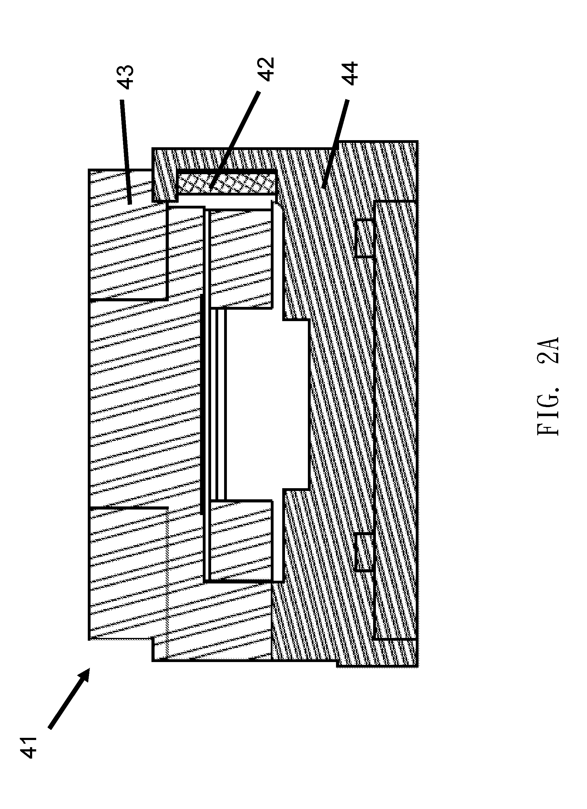
[0018]Please refer to FIG. 2A and FIG. 2B in correspondence with the following description. FIG. 2A and FIG. 2B are schematic diagrams illustrating a voice coil motor (VCM) 41 comprising a lens carrier 43 physically connected with a magnetic device, an electromagnetic driving apparatus 44, constructed by a coil, a magnetic sensing element 420 such as a Hall sensor, a storage media 421 and a controller 42. The storage media 421 and the controller 42 can be integrated together into a single chip or the storage media 421, and the magnetic sensing element 420 and the controller 42 can be integrated together into a single chip. The magnetic sensing element 420 detects a location of the lens carrier 43 and outputs a location value relating to the location of the lens carrier 43 via an amplifier 4201. The maximum working electrical range of the amplifier 4201 is defined as zero to the maximum native location value.

[0019]Briefly, as illustrated in FIG. 2B, the storage media 421 within the V...


PUM

PropertyMeasurementUnit
lengthaaaaaaaaaa
magnetic fieldaaaaaaaaaa
lengthaaaaaaaaaa

Abstract

A voice coil motor (VCM) includes a lens carrier physically connected to a magnetic device, an electromagnetic driving apparatus, constructed by a coil, a magnetic sensing element, a storage media and a controller. The magnetic sensing element detects a location of the lens carrier and outputs the location value relating to the location of the lens carrier via an amplifier. The storage media stores a gain value and an offset compensation value relating to the amplifier. The controller can make the lens carrier move between a top position and a bottom position in which the lens carrier can be moved within the voice coil motor. The lens carrier is moved using the coil interaction with a magnetic field of the magnetic device when current is applied to the coil.

Description

BACKGROUND OF THE INVENTION[0001]1. Field of the Invention[0002]The present invention relates to a voice coil motor, and more particularly, to a voice coil motor with a storage medium storing a gain value and an offset compensation value.[0003]2. Description of the Prior Art[0004]In order to perform a more accurate position control for a set of lenses or an access arm of a hard disk drive, a voice coil motor (VCM) is usually adopted to move the set of lenses or the access arm of the hard disk drive. The structure of a VCM is primarily a coil placed within a magnetic circuit including a permanent magnet.[0005]In an optical system employing a VCM, there is an interaction propelling force between the coil and the permanent magnet according to Fleming's left-hand rule that moves a carrier physically connected to the permanent magnet when a current flows through the coil; at the same time, a set of lenses which is attached to the carrier is moved correspondingly, so as to achieve optical...

Claims


Application Information

Patent Timeline
Patent Type & Authority Applications(United States)
IPC IPC(8): G11B11/00H02P25/06
CPCG11B21/025H02K33/18H02K33/02H02K41/0354H02K41/0356G02B7/02G02B7/09G03B3/10H02P7/025H02K2213/03G03B2205/0069H04N23/54
Inventor TSAI, CHING-LUNG
Owner VASSTEK INT
Why Eureka
Try Eureka