Automatic powder recycling apparatus

a technology of automatic powder recycling and powder, which is applied in the field of automatic powder recycling apparatus, can solve the problems of contaminating the whole three-dimensional object-forming machine, etc., and achieves the effect of expanding the function of the light source and avoiding the problem of polluting the working environmen

Inactive Publication Date: 2012-03-01
MICROJET TECH
View PDF5 Cites 81 Cited by
  • Summary
  • Abstract
  • Description
  • Claims
  • Application Information

AI Technical Summary

Benefits of technology

[0007]The present invention provides an automatic powder recycling apparatus for avoiding the problem of polluting the working environment during the processes of spreading powder, printing and taking out the finished product. As previously, the light source o

Problems solved by technology

During the processes of spreading powder, printing and taking out the finished product by the conventional rapid prototyping techno

Method used


Image

  • Automatic powder recycling apparatus
  • Automatic powder recycling apparatus
  • Automatic powder recycling apparatus

Examples


Embodiment Construction

[0018]The present invention will now be described more specifically with reference to the following embodiments. It is to be noted that the following descriptions of preferred embodiments of this invention are presented herein for purpose of illustration and description only. It is not intended to be exhaustive or to be limited to the precise form disclosed.

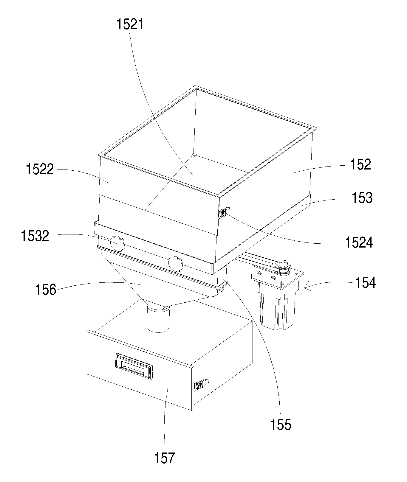
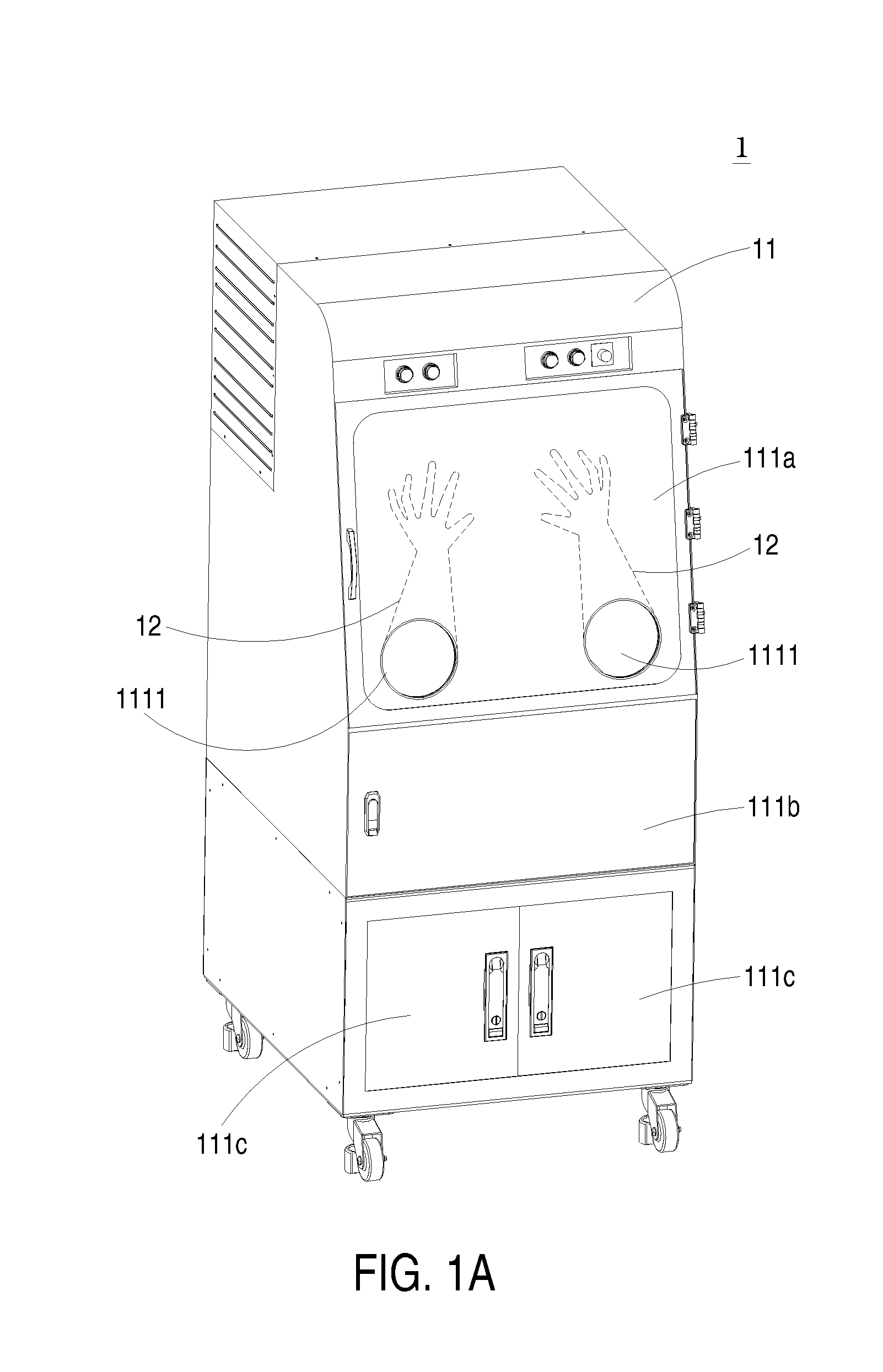
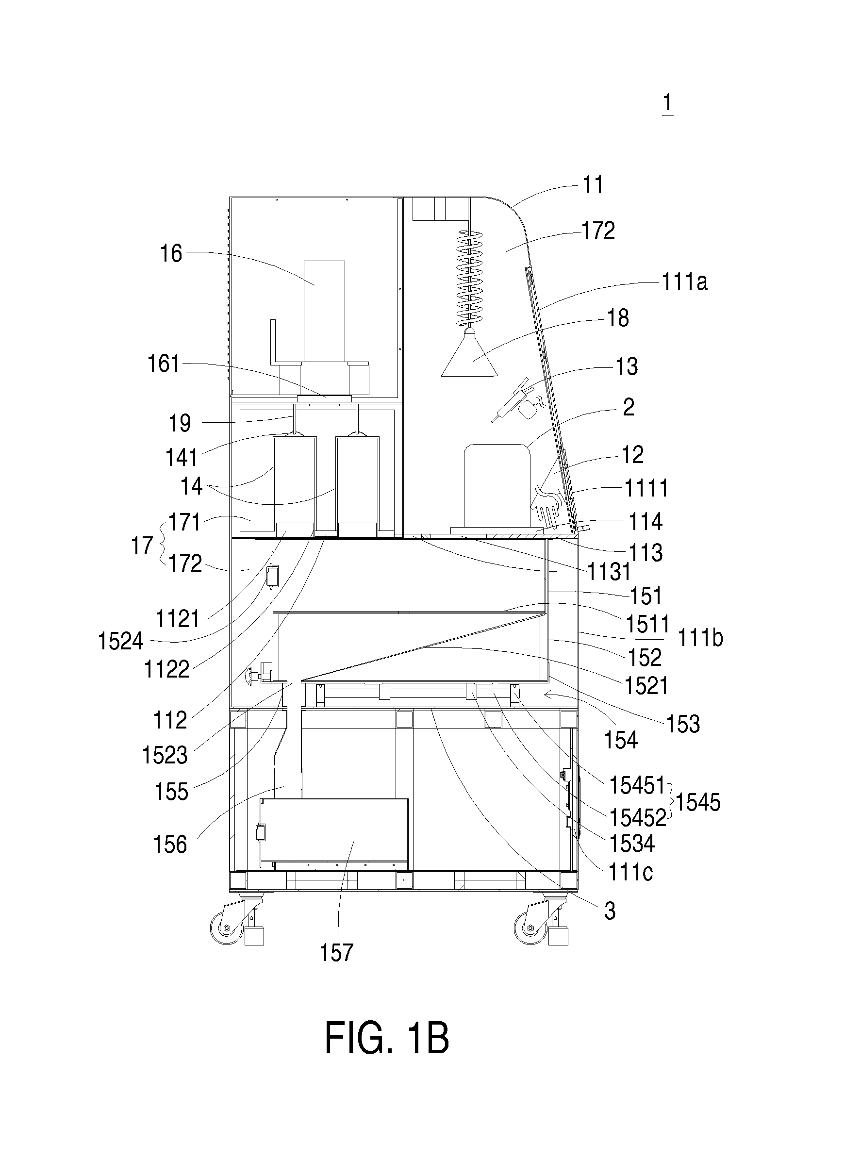
[0019]FIG. 1A is a schematic perspective view illustrating an automatic powder recycling apparatus according to an embodiment of the present invention. FIG. 1B is a schematic side view illustrating an automatic powder recycling apparatus of FIG. 1A. The automatic powder recycling apparatus 1 is applied to a three-dimensional object-forming system (not shown). The three-dimensional object-forming system has a three-dimensional object-forming mechanism (not shown) such as a floor three-dimensional object-forming mechanism for producing a three-dimensional physical model. The three-dimensional object-forming mechanism is disclosed i...


PUM

PropertyMeasurementUnit
Distanceaaaaaaaaaa

Abstract

An automatic powder recycling apparatus includes a housing, a plurality of isolation elements, an air-blowing device, a powder filtering member, a recycling member and an air-inhaling device. A sealed space is defined within the housing. The air-blowing device is disposed within the sealed space for removing the powder attached on the surface of the finished product. The air-inhaling device is in communication with the first receptacle for allowing the first receptacle to be in a negative pressure state. When the powder on the finished product is removed by the air-blowing device and directed to the powder filtering member by the air-inhaling device, the powder is filtered and blocked by the powder filtering member. When the air-inhaling device is disabled, the powder blocked by the powder filtering member naturally falls down to the recycling member.

Description

FIELD OF THE INVENTION[0001]The present invention relates to an automatic powder recycling apparatus, and more particularly to an automatic powder recycling apparatus for use in a three-dimensional object-forming system.BACKGROUND OF THE INVENTION[0002]The rapid prototyping (RP) technology is developed from the idea of forming a pyramid by stacking layers, and the main technical feature is to achieve fast formation. A complicated design can be transformed into a three-dimensional physical model automatically fast without any cutting tools, moulds and fixtures. Thus, the development cycle of new products and research and development cost are largely reduced to ensure time to market for new products and first-time-right ratio. Accordingly, a complete and convenient product design tool is provided between technicians and non-technicians (e.g. managers and users), and the product competitiveness and the quick reaction capability of enterprises in the market are improved obviously.[0003]...

Claims


Application Information

Patent Timeline
IPC IPC(8): B29B7/66
CPCB08B5/02B08B15/026B33Y30/00B22F2003/1059B29C67/0085B22F3/1055Y02P10/25B22F10/20B22F12/38B22F12/226B22F10/73Y02P10/20
Inventor CHEN, CHIH-KAIHUANG, KE-MINGSHI, KWO-YUAN
Owner MICROJET TECH
Why Eureka
Try Eureka