Refrigeration apparatus

a refrigeration apparatus and refrigeration technology, applied in the field of space cooling systems, to achieve the effect of maximizing the sub-cooling of main liquid, less time, and improving the life span of compressors

Inactive Publication Date: 2012-03-08
STANDEX INT CORP
View PDF10 Cites 33 Cited by
  • Summary
  • Abstract
  • Description
  • Claims
  • Application Information

AI Technical Summary

Benefits of technology

[0014]The invention is an extra low temperature refrigeration system consisting of a two-stage compressor that has an electronic controller. The electronic controller controls an electric expansion valve in the evaporator, which modulates the true superheat. There is also an electric pressure control valve in the condenser, which modulates the head pressure in cool mode, and the suction pressure in defrost mode. The defrost cycle uses a reversing valve. The liquid refrigerant for the inter-stage sub-cooling circuit is constantly provided by a sub-condenser separated from the conventional one condenser system. Therefore, the system provides constant cooling for the compressor motor windings as the compressor runs. There is a one-way pathway from the main condenser circuit to the sub-condenser circuit. This pathway will call for more refrigerant from the main circuit to the sub-cooling circuit as demanded. The inter-stage sub-cooling circuit uses an electric expansion valve true superheat control for its sub-cooler. This accurate cooling of superheat improves the life span the compressor and maximizes the main liquid sub-cooling. The reverse cycle defrost method, which is disclosed in U.S. Pat. No. 7,073,344, permits the defrosting the evaporator system in less time required for conventional defrost methods. The reverse flow during defrost also brings the lubrication oil back to the compressor. This cooling system also eliminates the need for a mechanical head pressure control valve and many check valves typically seen in conventional systems. The lower head pressure operation allows energy savings during low ambient conditions. Also, the system uses a liquid reservoir to store extra refrigerant charge. The liquid reservoir acts as a liquid receiver for cooling mode and a refrigerant surge protection tank for defrosting mode. The system uses an oil differential pressure switch as a digital input to the main controller to initiate defrost for proper oil return when the oil pressure falls below a permitted pressure level. Further, the system uses a temperature-sensing probe mounted at the compressor suction copper tubing to measure the compressor true superheat. The compressor true superheat is controlled by varying the evaporator electric expansion valve opening in order to protect the compressor from overloading and liquid refrigerant flood-back. The evaporator uses compressor-discharged vapor to defrost the drain pan. The drain pan piping is paralleled to the refrigerating circuit piping which is not seen in previous reverse cycle defrost systems. This reduces pressure drop of reverse flow and offers a fast and clean defrost throughout the evaporator coil.

Problems solved by technology

However, there is not found in the prior art an extra low temperature refrigeration system that combines the features of dual valve control, dual circuit condenser design, superheat control on the sub-cooler circuit, a liquid receiver to store extra refrigerant charge, an oil-pressure initiated defrost, parallel hot gas drain pan loop design on the evaporator to defrost the drain pan, and a compressor superheat control that will provide performance and protection features and lower head pressure to achieve high reliability and substantial operating cost savings.

Method used


Image

  • Refrigeration apparatus
  • Refrigeration apparatus
  • Refrigeration apparatus

Examples


Embodiment Construction
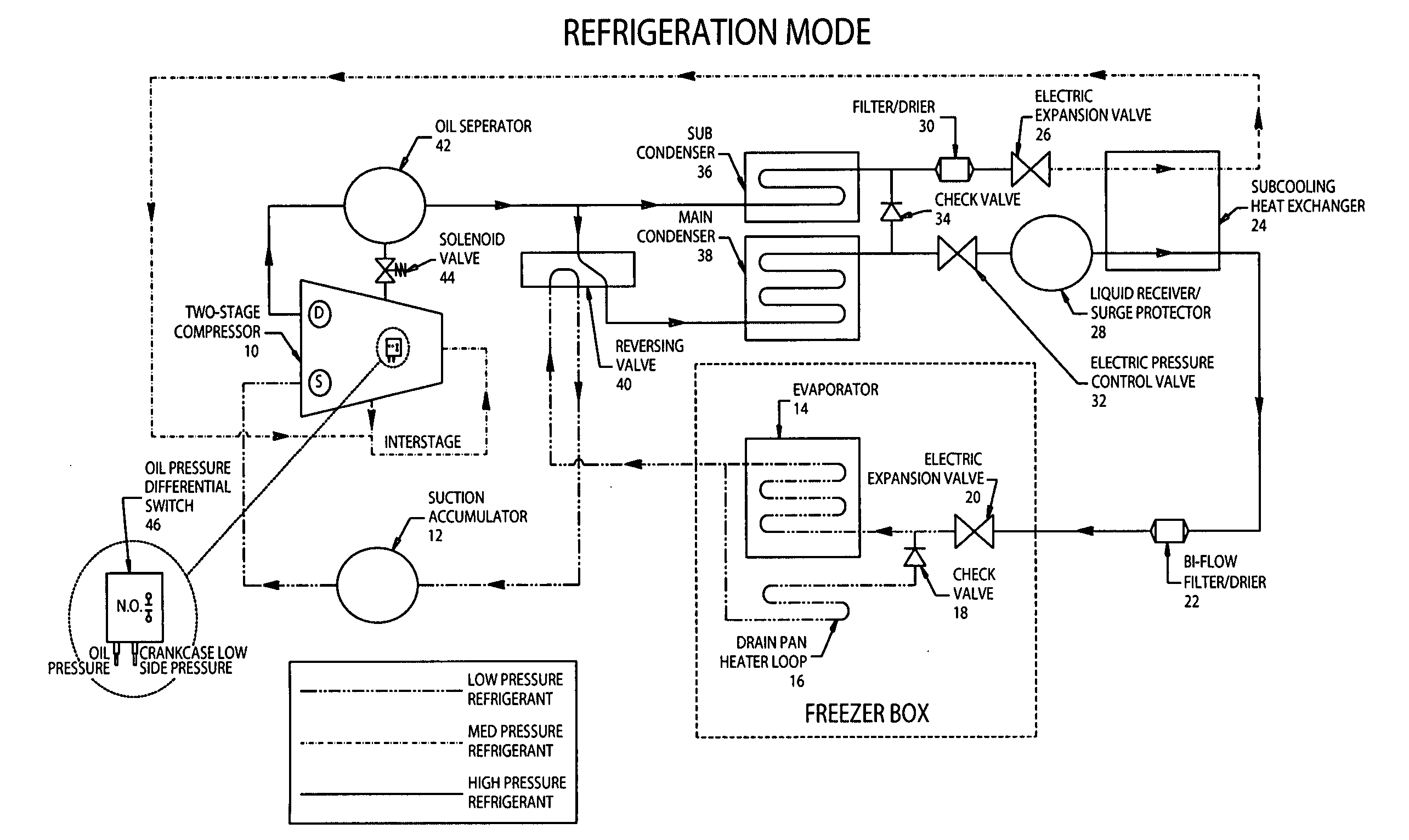
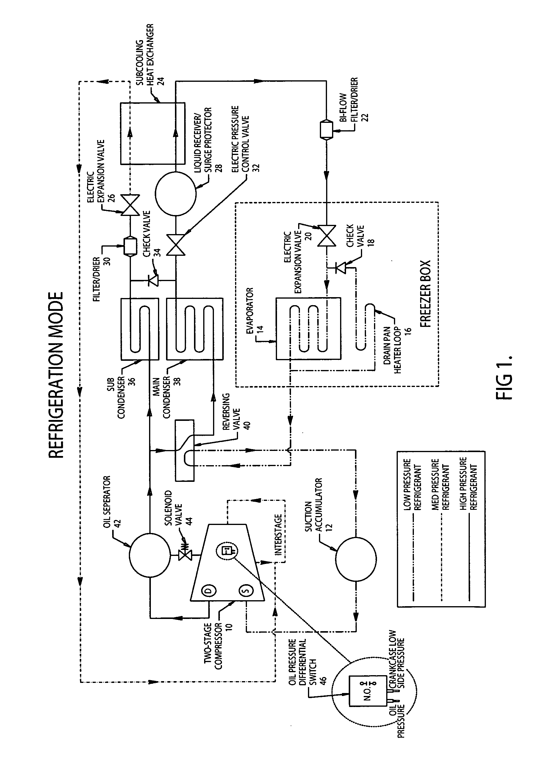
Refrigeration Mode:

[0017]As shown in FIG. 1, invention utilizes two-stage reciprocating compressor 10. Refrigerant (not shown) is compressed by compressor 10. The temperature and pressure of the refrigerant is raised. The hot pressurized refrigerant gas then flows through the oil separator 42. The refrigerant oil is then separated by 42 and discharged back to the compressor 10 crankcase. Oil return solenoid valve 44 is powered with the synchronization of the compressor 10. When compressor 10 is in operation, solenoid valve 44 is open allowing oil to flow through.

[0018]The refrigerant after oil separator 42 is diverted into two directions. The first direction goes to the main circuit condenser 38 through the four way reversing valve 40. The second direction is to the sub-circuit condenser 36.

[0019]The majority of the high-pressure refrigerant goes to main condenser 38 and is condensed into a liquid state. Electric pressure control valve 32 is used to modulate the pressure of the refr...


PUM


Abstract

An extra low temperature refrigeration system consisting of a two-stage compressor that has an electronic controller. The electronic controller controls an electric expansion valve in the evaporator, which modulates the true superheat. There is also an electric pressure control valve in the condenser, which modulates the head pressure in cool mode, and the suction pressure in defrost mode. The defrost cycle uses a reversing valve. The liquid refrigerant for the inter-stage sub-cooling circuit is constantly provided by a sub-condenser separated from a conventional one condenser system. Therefore, the system provides constant cooling for the compressor motor windings as the compressor runs. There is a one-way pathway from the main condenser circuit to the sub-condenser circuit. This pathway will call for more refrigerant from the main circuit to the sub-cooling circuit as demanded. The inter-stage sub-cooling circuit uses an electric expansion valve true superheat control for its sub-cooler.

Description

[0001]This application claims benefit under Title 35 U.S.C 119(e) of U.S. Provisional Application Ser. No. 61 / 402,657 filed Sep. 1, 2010.FIELD OF THE INVENTION[0002]This invention relates generally to space cooling systems, in particular to a low temperature refrigeration apparatus for providing space cooling with significant energy and cost savings.BACKGROUND OF THE INVENTION[0003]A typical space cooling system includes at least one evaporator system contained within the space that is to be cooled, a condenser system that is located outside of the cooled space, and a compressor positioned between the condenser system outlet and the evaporator system inlet and, finally, an expansion valve which completes the loop joining together the condenser system outlet and the evaporator system inlet. A refrigerant is circulated within the loop, which cools the space as follows. The refrigerant is compressed by the compressor, which raises the temperature and pressure of the refrigerant. The ho...

Claims


Application Information

Patent Timeline
Patent Type & Authority Applications(United States)
IPC IPC(8): F25B41/04
CPCF25B1/10F25B6/02F25B2400/13F25B47/025F25B49/027F25B40/02
Inventor LUO, RANOWEN, KENNETH W.
Owner STANDEX INT CORP
Why Eureka
Try Eureka