Glass-Melting Device for Producing Glass Fiber and Method for Producing Glass Fiber Using Same

Active Publication Date: 2012-03-08
NITTO BOSEIKI CO LTD
View PDF6 Cites 4 Cited by
  • Summary
  • Abstract
  • Description
  • Claims
  • Application Information

AI Technical Summary

Benefits of technology

[0038]The present invention enables mixing of bubble

Problems solved by technology

However, bubbles are unfavorably generated during melting.
Due to these bubbles, some bubbles may exist in glass fibers during subsequent spinning When this happens, glass fiber yar

Method used


Image

  • Glass-Melting Device for Producing Glass Fiber and Method for Producing Glass Fiber Using Same
  • Glass-Melting Device for Producing Glass Fiber and Method for Producing Glass Fiber Using Same
  • Glass-Melting Device for Producing Glass Fiber and Method for Producing Glass Fiber Using Same

Examples


first embodiment

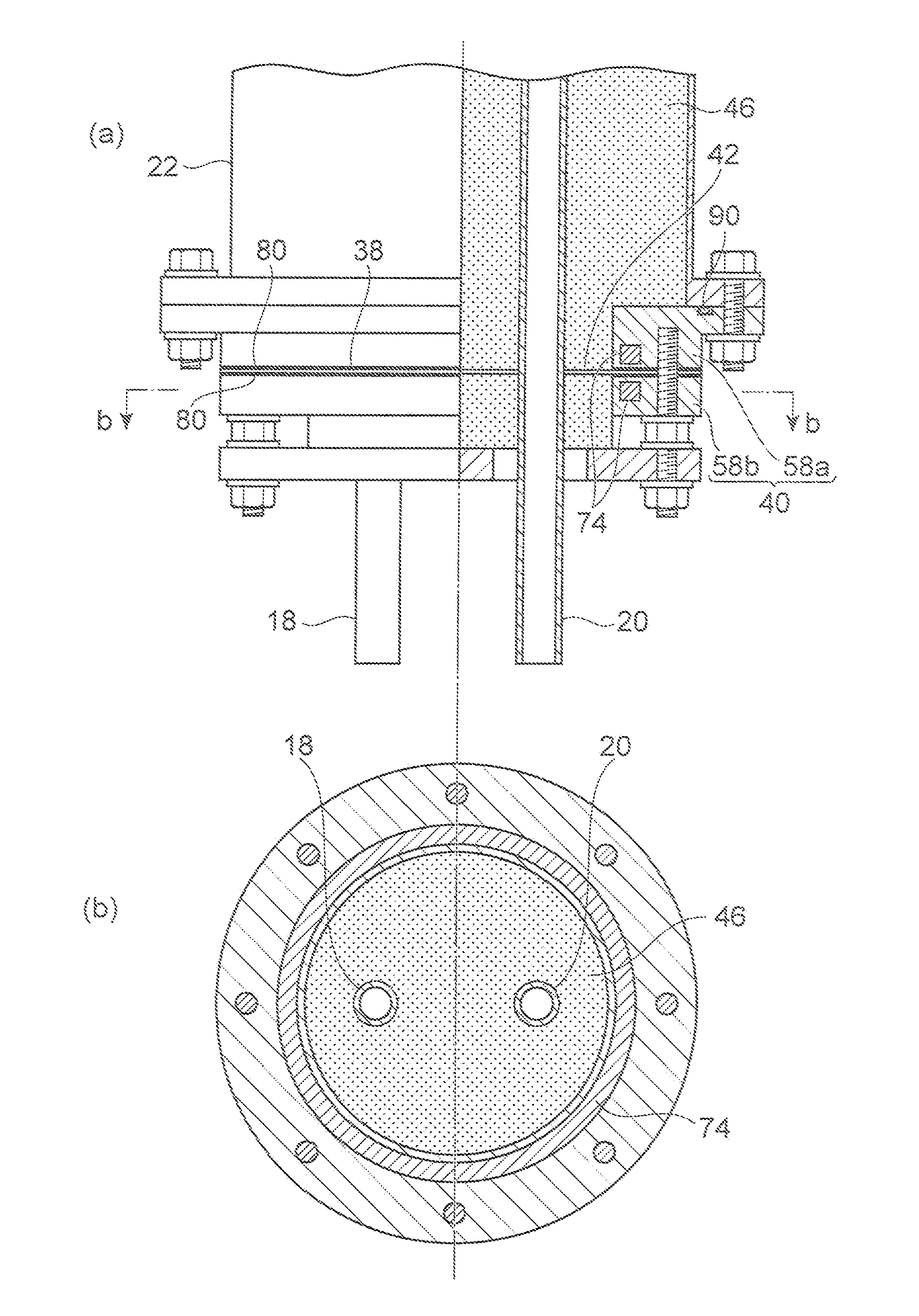
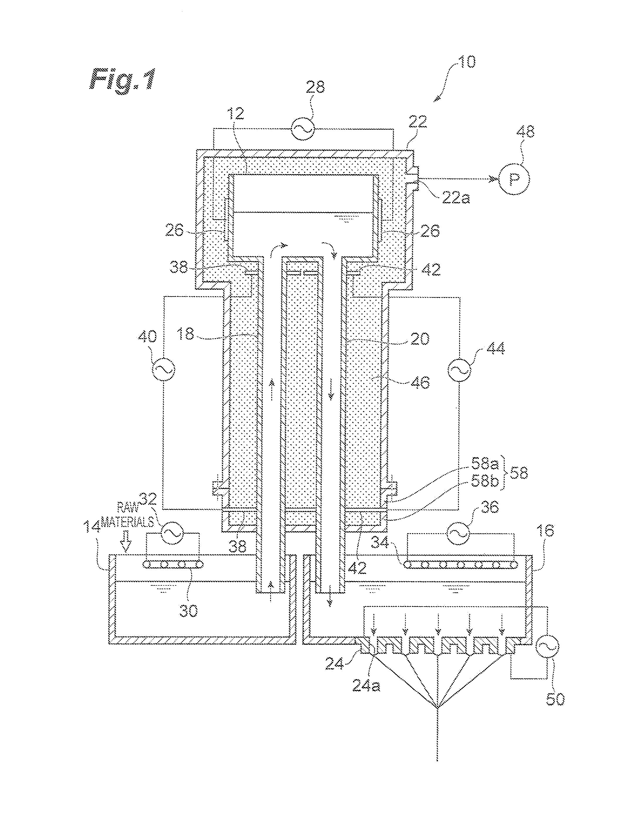
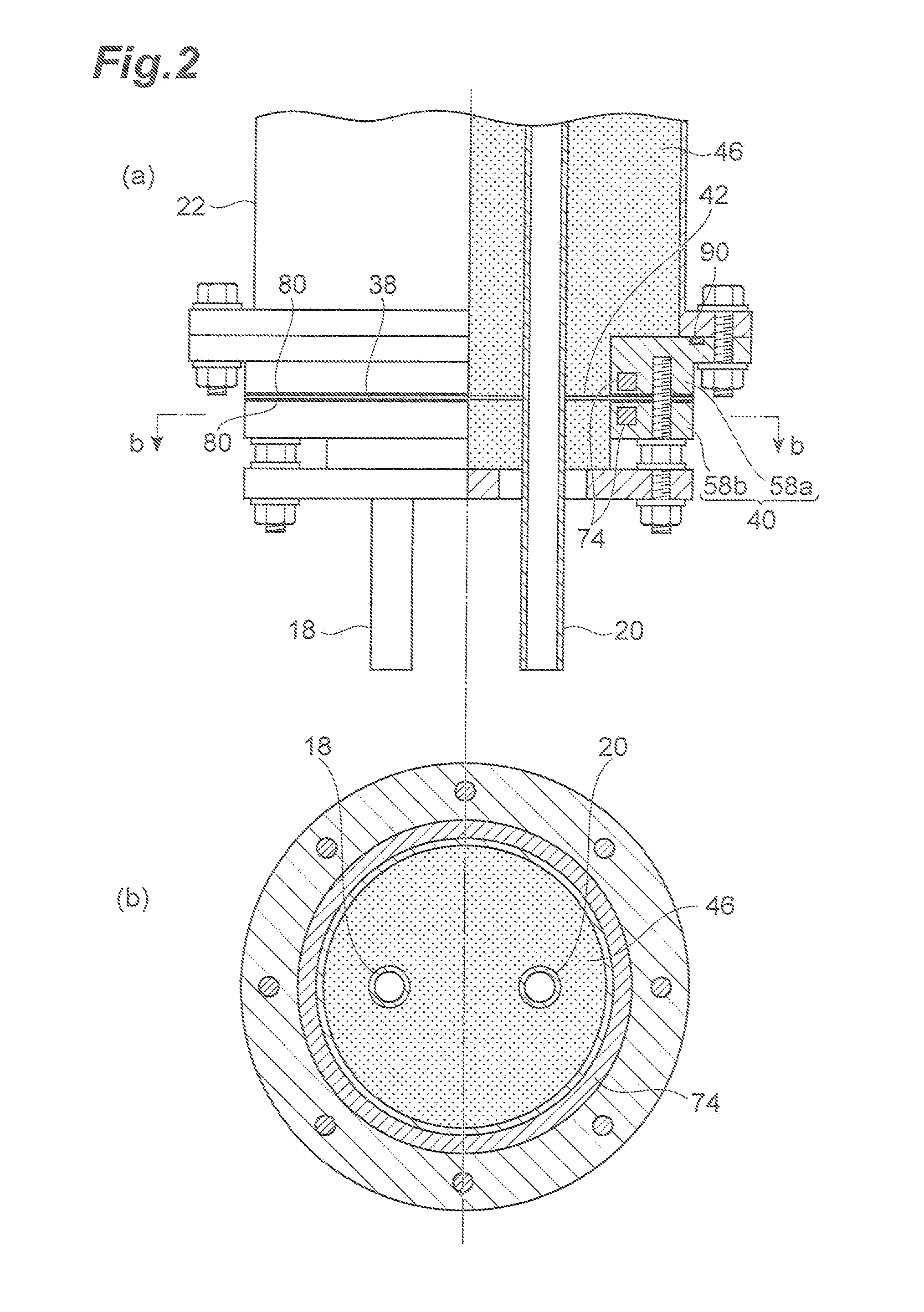
[0055]FIG. 1 is a cross-sectional diagram showing a configuration of a glass-melting device for producing glass fibers according to a first embodiment. As illustrated in FIG. 1, a glass-melting device 10 for producing glass fibers (hereinafter also referred to as “glass-melting device”) includes a first glass-melting tank 12, a second glass-melting tank 14, a third glass-melting tank 16, an ascending conduit 18, a descending conduit 20, a decompression housing 22 and a bushing 24.

[0056]The first glass-melting tank 12 heats molten glass and maintains the temperature of the molten glass, and an upper part of the first glass-melting tank 12 is opened.

[0057]The first glass-melting tank 12 includes heating means for heating molten glass and maintaining the temperature of the molten glass. The heating means includes a pair of electrode parts 26 connected to opposing side surfaces of the first glass-melting tank 12, and a power supply 28 that supplies current to the electrode parts 26. The...

second embodiment

[0112]Next, a second embodiment will be described with reference to FIGS. 3 to 5. A glass-melting device 110 for producing glass fibers according to a second embodiment has a configuration that is basically the same as that of the glass-melting device 10 for producing glass fibers according to the first embodiment. The glass-melting device 110 for producing glass fibers is different from the glass-melting device 10 for producing glass fibers according to the first embodiment only in that: an ascending conduit and a descending conduit are composed of one double tube; and partition plates are provided to a first glass-melting tank 12. Thus, a description will be provided below only for points of difference from the first embodiment, and a description of points that are the same as those of the first embodiment will be omitted.

[0113]FIG. 3 is a cross-sectional diagram showing a configuration of a glass-melting device for producing glass fibers according to a second embodiment. FIG. 4 i...

third embodiment

[0138]Next, a third embodiment will be described with reference to

[0139]FIG. 7. A glass-melting device 210 for producing glass fibers according to a third embodiment has a configuration that is basically the same as that of the glass-melting device 110 for producing glass fibers according to the second embodiment. The glass-melting device 210 for producing glass fibers is different from the glass-melting device 110 for producing glass fibers according to the second embodiment only in a configuration of a housing covering a first glass-melting tank 12, an ascending conduit part 52 and a descending conduit part 54. Thus, only points of the difference from the second embodiment will be described below, and a description of points that are the same as the second embodiment will be omitted.

[0140]FIG. 7 is a cross-sectional diagram showing a configuration of a glass-melting device for producing glass fibers according to a third embodiment.

[0141]As illustrated in FIG. 7, the glass-melting ...


PUM

PropertyMeasurementUnit
Lengthaaaaaaaaaa
Pressureaaaaaaaaaa
Areaaaaaaaaaaa

Abstract

An object of the present invention is to effectively reduce mixing of bubbles into a spun glass fiber.
A glass-melting device 10 for producing glass fibers includes: a first glass-melting tank 12 exposed to a reduced-pressure atmosphere; a second glass-melting tank 14 and a third glass-melting tank 16 arranged below the first glass-melting tank 12; an ascending conduit 18 that sends up molten glass resulting from melting in the second glass-melting tank 14 to deliver the molten glass to the first glass-melting tank 12; a descending conduit 20 that sends the molten glass down from the first glass-melting tank 12 to deliver the molten glass to the third glass-melting tank 16; a decompression housing 22; and a bushing 24. The glass-melting device 10 further includes heating means for separately heating the first glass-melting tank 12, the second glass-melting tank 14, the third glass-melting tank 16, the ascending conduit 18, the descending conduit 20 and the bushing 24.

Description

TECHNICAL FIELD [0001]The present invention relates to a glass-melting device for producing glass fibers which melts glass raw materials for spinning glass fibers, and a method for producing glass fibers using the same.BACKGROUND ART [0002]A direct melt process and a marble melt process have been used in the production of glass fibers as typical melting methods for forming a plurality of glass fibers by fiberizing a molten glass, gathering the glass fibers, and spinning them as glass fiber yarn. In the direct melt process, powders or particulate matters of various mineral matters are mixed as glass raw materials, injected into a melting furnace, and melted to produce a molten glass. On the other hand, in the marble melt process, glass gobs referred to as marbles prepared by solidifying a molten glass are remelted to produce a molten glass (for example, see Patent Literature 1).[0003]For spinning glass fibers, glass raw materials of mineral matters are melted as described above. Howe...

Claims


Application Information

Patent Timeline
IPC IPC(8): C03B37/085C03B37/01
CPCC03B5/187C03B5/20C03B37/0203C03B5/235C03B37/085C03B5/2252C03B37/02C03B37/083
Inventor HIRAYAMA, NORIOTAKAHASHI, MASAHIKOMIYANAGA, NAOHIROOGAWA, KENTAROU
Owner NITTO BOSEIKI CO LTD
Why Eureka
Try Eureka