Wheel rim, and wheel and vehicle using same

a technology of wheel rims and wheels, which is applied in the direction of disc wheels, vehicle components, road vehicles, etc., can solve the problems of high deformation of side portions and bead portions of tires, deterioration of rubber parts, and high deformation of tire bead parts, so as to reduce the increase of tire temperature during running, high heat emissivity, and high heat absorption

Inactive Publication Date: 2012-03-08
SUMITOMO RUBBER IND LTD
View PDF8 Cites 3 Cited by
  • Summary
  • Abstract
  • Description
  • Claims
  • Application Information

AI Technical Summary

Benefits of technology

[0019]According to the embodiment of claim 1, the pneumatic tire is mounted on the metallic wheel rim, and the coating having high heat emissivity is formed on at least a part of the surface of the wheel rim. Therefore, the heat energy radiated form the tire transfers efficiently to the vehicle through the coating having high heat absorptance, and is released to the outside. Therefore, the increase of the tire temperature during running can be reduced, and the tire durability improves.
[0020]According to the embodiment of claim 2 or 3, the painted coating in black or the coating having heat emissivity of not less than 0.8 is used as the coating having high heat absorptance. In this way, the above-mentioned effect is certainly produced because the coating having high heat emissivity also has high heat absorptance.
[0021]According to the embodiment of claim 4, to provide with the coating in the first surface which does not exposed to the outside air in a tire-mounted state helps efficiently transferring the heat energy of the tire to the vehicle side and helps curbing the increase of the tire temperature. In particular, according to the embodiment of claim 5, it is preferable that the first surface is an outer circumferential surface of the body portion extending between rim sheet portions. The body portion, which is faced with the tire cavity surface (inner liner, for example), can absorb more efficiently the heat energy radiated from the tire cavity surface
[0022]Moreover, in accordance with the embodiment of claim 6, the coating can be formed also in the second surface which is not exposed to the outside air at the tire mounting. In this case, the heat energy from the tire, which is absorbed by the coating formed on the surface of the first surface, can efficiently release from the coating formed on the second surface to the outside air. So, the tire temperature can be efficiently reduced through the wheel rim.
[0023]According to the embodiment of claim 7 or 9, the above wheel rim is preferably used for the wheel on which the pneumatic tire is mounted and / or for the vehicle comprising such a wheel.
[0024]Especially, according to the embodiment of claim 8, when the above-mentioned pneumatic tire is the run flat tire being apt to generate heat, the present invention has profound effects.BRIEF EXPLANATION OF DRAWING

Problems solved by technology

Owing to the heat generation, the heat deteriorates the rubber portion; eventually, the tire comes to destruction.
Such destruction occurs from a side portion and a bead portion of the tire which highly deforms during running.
However, each of the above methods had increased a tire weight and a longitudinal spring constant.
In the conventional methods, there was a problem of increasing unsprung weight of the vehicle, deteriorating steering stability, and causing deteriorations of ride comfort and fuel efficiency.

Method used


Image

  • Wheel rim, and wheel and vehicle using same
  • Wheel rim, and wheel and vehicle using same
  • Wheel rim, and wheel and vehicle using same

Examples


example

[0063]To ascertain the efficacy of the present invention, test wheel rims (size: 18×8−J) were made based on the basis of the specifications shown in Table 1. On each of the test wheel rims, a painted coating i n black was formed with colorant in black (THI-1B) manufactured by TASCOJAPAN CO., LTD.

[0064]A run flat tire of 245 / 40ZR18 was mounted on each of the wheel rims for all wheels of a domestically produced passenger vehicle. From one wheel of the all wheels, a valve core was removed, and the internal pressure thereof was set to be zero. The above-mentioned passenger vehicle ran on a test course (weather: fine; Air temperature: 22 degrees C.) at a speed of 60 km / h. Durability test was conducted until the tire broke down. Evaluation was displayed using indices with a running distance of Example 1 being 100. The larger the numeric value was, the better the durability was. The test results are shown in Table 1.

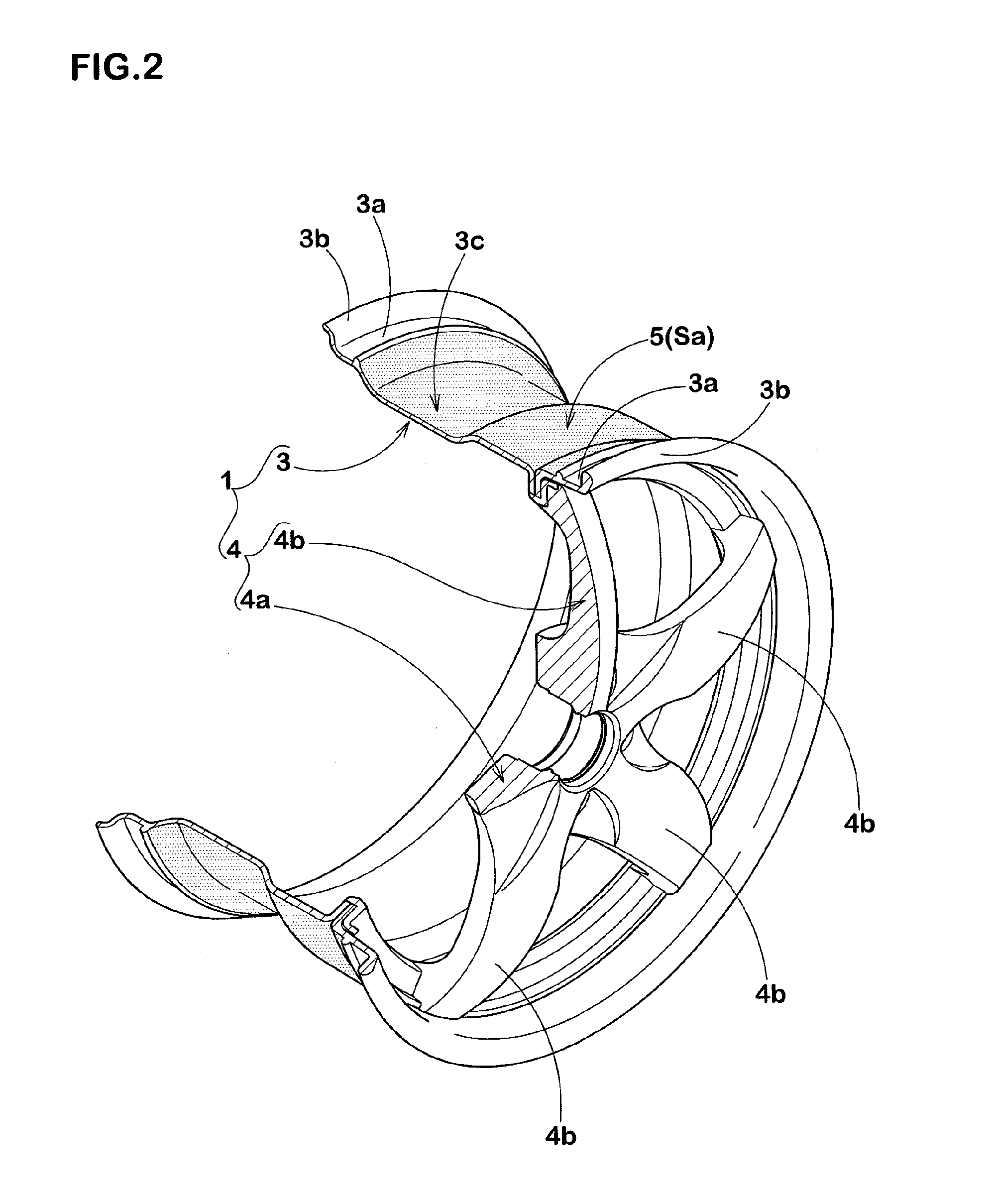
TABLE 1Com. Ex. 1Ex. 1Ex. 2Ex. 3Drawing showing position ofNoFIG. 2FIG. 3F...


PUM


Abstract

A wheel rim configured to enhance the durability of the tire by reducing the temperature of the tire during running. A wheel rim 1 consisting of a metallic material and adapted so that a pneumatic tire 2 is mounted thereon, wherein a coating 5 having high heat emissivity is formed on at least a part of the surface of the wheel rim 1.

Description

TECHNICAL FIELD[0001]The present invention relates to a wheel rim configured to enhance the durability of the tire by reducing the temperature of the tire during running, and relates to a wheel and a vehicle using the wheel rim.BACKGROUND OF THE INVENTION[0002]A tire deflects repeatedly during running, and heat generates in a rubber portion of the tire. Owing to the heat generation, the heat deteriorates the rubber portion; eventually, the tire comes to destruction. Such destruction occurs from a side portion and a bead portion of the tire which highly deforms during running. To prevent the destruction of the tire, those in the art had tried to reduce an amount of the deformation previously. For example, following methods were proposed:[0003]a method of using hard rubber for the bead apex positioned in the bead portion,[0004]a method of sizing up the bead apex,[0005]a method of reinforcing the bead portion with a bead filler made of cord material, and / or[0006]a method of improving r...

Claims


Application Information

Patent Timeline
Patent Type & Authority Applications(United States)
IPC IPC(8): B60B21/00
CPCB60B3/044B60B3/10B60B21/108B60B25/002B60C17/0009B60B2310/616B60B2310/6162B60B2900/513B60Y2200/11B60B25/22B60B21/00B60B21/12B60C17/00
Inventor HINO, HIDEHIKO
Owner SUMITOMO RUBBER IND LTD
Why Eureka
Try Eureka