Method and apparatus for transmitting and receiving duplicate data in a multicarrier wireless communication system

a wireless communication system and wireless communication technology, applied in the field of wireless communication systems, can solve the problems of reducing and affecting the so as to increase the probability of successful transmission and reception of important data, and increase the probability of successful data transmission and reception.

Inactive Publication Date: 2012-03-08
LG ELECTRONICS INC
View PDF4 Cites 236 Cited by
  • Summary
  • Abstract
  • Description
  • Claims
  • Application Information

AI Technical Summary

Benefits of technology

[0021]According to the present invention, the probability of successful data transmission and reception can be increased in a system supporting a carrier aggregation technique using a plurality of CCs. Moreover, the probability of successful transmission and reception of important data can be selectively increased.
[

Problems solved by technology

However, it is not easy to allocate frequency of a wide bandwidth except in some areas of the world.
However, if a UE is located at a cell edge and runs short of power, since sufficient energy cannot be used for data transmission during a short TTI, the probability of succes

Method used


Image

  • Method and apparatus for transmitting and receiving duplicate data in a multicarrier wireless communication system
  • Method and apparatus for transmitting and receiving duplicate data in a multicarrier wireless communication system
  • Method and apparatus for transmitting and receiving duplicate data in a multicarrier wireless communication system

Examples


embodiment 1

[0091]The first embodiment of the present invention is described with reference to FIG. 9.

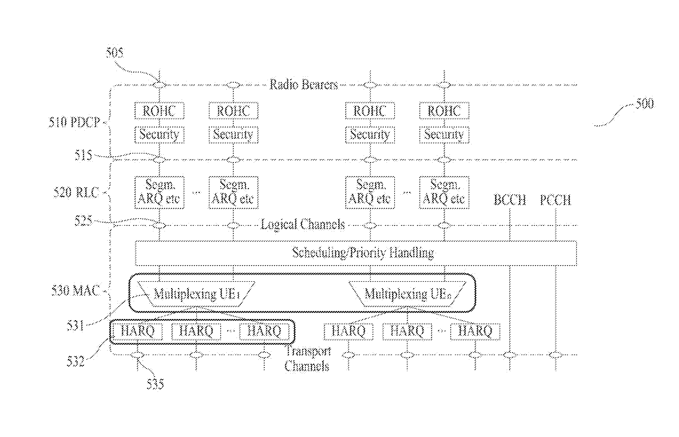
[0092]FIG. 9 illustrates a UL L2 architecture including a PDCP layer 910, an RLC layer 920, and a MAC layer 930. In this embodiment, a duplication entity 932 is defined in the MAC layer 930 of a transmitter. The duplication entity 932 may generate a plurality of duplicated MAC PDUs from one MAC PDU transmitted by a multiplexing entity 931 of the MAC layer 930 and transmit the duplicately generated MAC PDUs to HARQ entities 933-1, 933-2, . . . , 933-N corresponding to N CCs (FIG. 9 shows an example of N=5). The HARQ entities 933-1, 933-2, . . . , 933-N may simultaneously transmit the MAC PDUs to a receiver using independent RV values.

[0093]Specifically, a UE may receive a UL grant for duplication transmission from an eNB. The UE may receive the UL grant for duplication transmission through a specific DL CC (or specific cell) designated by the eNB or through all DL CCs (or all cells). When the UL...

embodiment 2

[0099]The second embodiment of the present invention is described with reference to FIG. 10.

[0100]FIG. 10 illustrates a UL L2 architecture including a PDCP layer 1010, an RLC layer 1020, and a MAC layer 1030.

[0101]In this embodiment, a duplication entity 1032 is defined in the MAC layer 1030 of a transmitter. The duplication entity may generate a plurality of duplicated MAC PDUs from one MAC PDU transmitted by a multiplexing entity 1031 and transmit the duplicately generated MAC PDUs to HARQ entities 1033-1, 1033-2, . . . , 1033-N corresponding to N CCs (FIG. 10 shows an example of N=5). The HARQ entities 1033-1, 1033-2, . . . , 1033-N may simultaneously transmit the MAC PDUs to a receiver using different RV values.

[0102]Specifically, a UE receives a UL grant for duplication transmission from an eNB. The UE may receive the UL grant for duplication transmission through a specific DL CC (or specific cell) designated by the eNB or through all DL CCs (or all cells). When the UL grant fo...

embodiment 3

[0114]The third embodiment of the present invention is described with reference to FIG. 11.

[0115]FIG. 11 illustrates a UL L2 architecture including a PDCP layer 1110, an RLC layer 1120, and a MAC layer 1130. In this embodiment, a duplication entity 1132 is defined in the MAC layer 1130 of a receiver and the receiver receives duplicated data from a transmitter.

[0116]Specifically, a UE may receive DL assignment for duplication reception from an eNB. The UE may receive the DL assignment for duplication reception through a specific DL CC designated by the eNB or through all DL CCs. When the DL assignment for duplication reception is transmitted through a specific CC, if the UE receives one DL assignment for duplication reception, the duplicated MAC PDUs are received through all DL CCs.

[0117]The DL assignment may be transmitted through a PDCCH masked to a C-RNTI of the UE. Alternatively, the eNB may allocate an RNTI (e.g. D-RNTI) which is newly defined to indicate the DL assignment for d...


PUM


Abstract

The present invention relates to a wireless communication system, and more particularly, discloses a method and an apparatus for transmitting and receiving duplicate data in a multicarrier wireless communication system. According to one embodiment of the present invention, a method in which a transmitter, which supports carrier aggregation for performing communication using N (N≧2) component carriers, transmits duplicate data, comprises the steps of: generating, in a media access control (MAC) layer of the transmitter, N duplicate data using radio link control (RLC) protocol data units (PDUs) from an RLC layer, and simultaneously transmitting, to a receiver, the respective N duplicate data on the N component carriers through respective N hybrid automatic repeat and request (HARQ) entities.

Description

TECHNICAL FIELD[0001]The following description relates to a wireless communication system, and more particularly, to a method and apparatus for transmitting and receiving duplication data in a wireless communication system supporting multiple carriers.BACKGROUND ART[0002]In a general wireless communication system, only one carrier is considered even though different uplink (UL) and downlink (DL) bandwidths are configured. For example, a wireless communication system in which the number of carriers constituting each of UL and DL is 1 and a UL bandwidth and a DL bandwidth are generally symmetrical may be provided based on a single carrier.[0003]In the International Telecommunication Union (ITU), an IMT-Advanced candidate technique demands support of an extended bandwidth compared with a conventional wireless communication system. However, it is not easy to allocate frequency of a wide bandwidth except in some areas of the world. Accordingly, as a technique for efficiently using a frag...

Claims


Application Information

Patent Timeline
IPC IPC(8): H04W72/04H04W4/00
CPCH04L1/0002H04L1/08H04L1/1819H04L2001/0096H04L1/1887H04L1/189H04L5/001H04L1/1822H04L1/1812
Inventor PARK, SUNG JUNYI, SEUNG JUNECHUN, SUNG DUCK
Owner LG ELECTRONICS INC
Why Eureka
Try Eureka