
Everting deployment system and handle

a technology of stent and handle, which is applied in the field of deployment systems, can solve the problems of affecting the integrity of the coating, reducing or completely losing function, and affecting and achieves the effect of improving the accuracy of the deployment location of the sten

Active Publication Date: 2012-03-08
COOK MEDICAL TECH LLC
View PDF15 Cites 109 Cited by
  • Summary
  • Abstract
  • Description
  • Claims
  • Application Information

AI Technical Summary

Benefits of technology

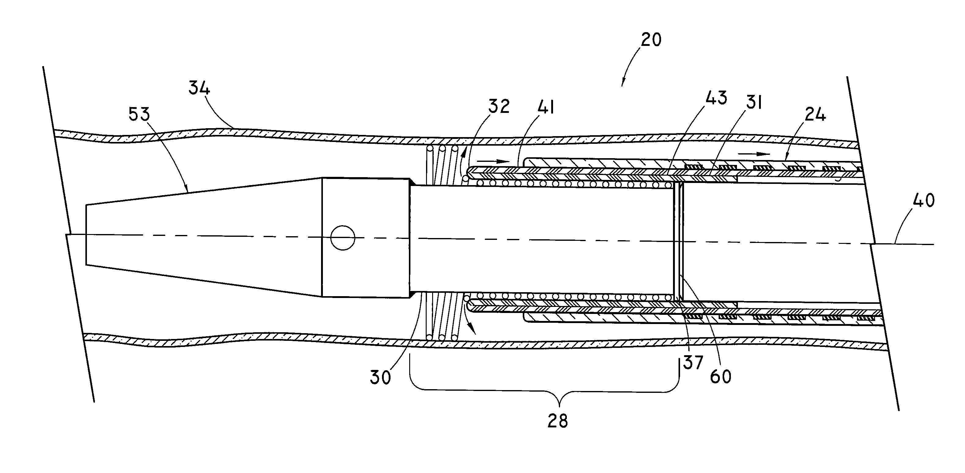
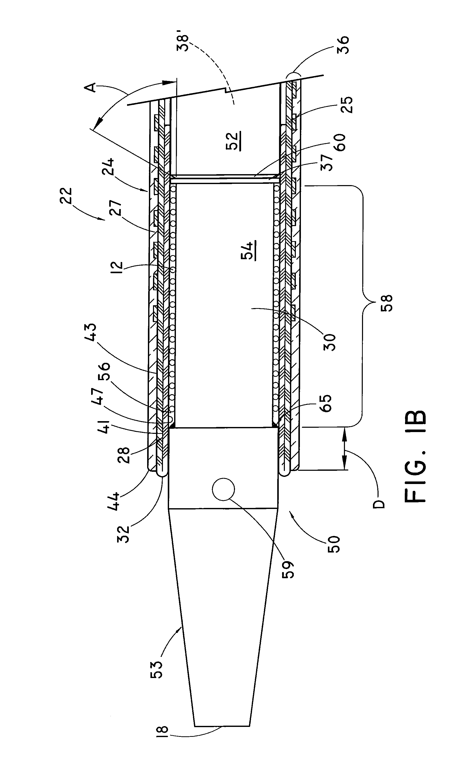
[0010]Accordingly, a stent deployment system, handle, and method of loading of a medical device are provided. The stent deployment system may be particularly useful for tubular medical devices having longer lengths of about 140 mm or longer. Another example of an application for the stent deployment system is for tubular medical devices that have been coated with a therapeutic agent and / or have a graft material. The stent deployment system may also provide flushing capabilities, and may be adapted to ensure that the tubular medical device does not jump forward during deployment thus providing enhanced accuracy of the stent deployed location.
[0012]The inner liner may include a lubricious material to permit sliding interactions more easily between the inner and outer portions of the everted inner liner. The inner liner may also include a low durometer material or a sticky material to enhance the frictional contact between the inner liner and the tubular medical device when loaded and prevent stent jumping. The extended portion of the inner liner may also have a larger diameter more proximal to a portion with a smaller diameter to facilitate inversion of the inner liner. A weakened region can be formed in the tubular wall of the outer catheter, and is particularly useful when splitting the tubular wall. The weakened region can be oriented axially and sized to be at least as long as the tubular medical device. The weakened region may also be defined by a discontinuous structural layer axially along the tubular wall so that it includes only a polymer material. It is preferable to position the weakened region at the proximal end of the outer sheath.
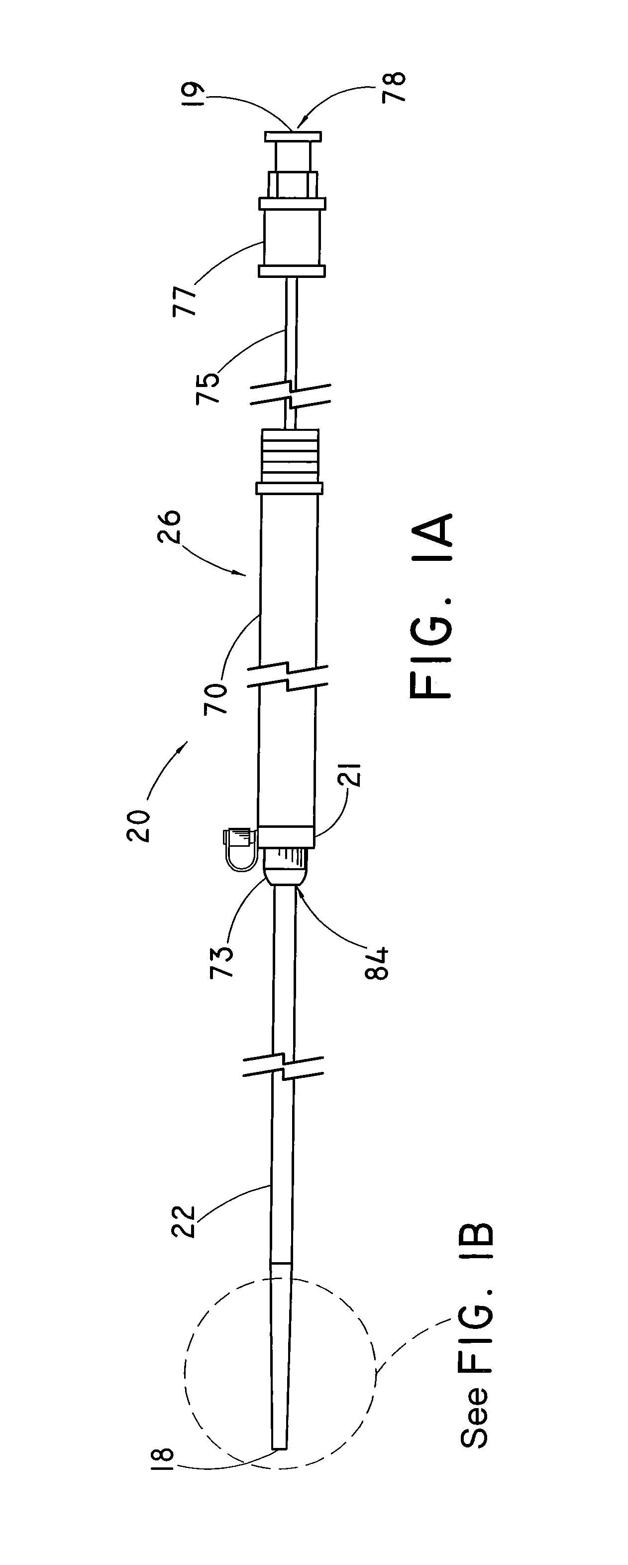
[0015]In another embodiment, a handle is provided for a stent deployment system that has a tubular member with a wall defining a lumen about a longitudinal axis between a proximal end and a distal end. The tubular member may be the outer catheter of the stent deployment system described above or another tubular member. The handle includes a housing having a cavity and a port configured to receive the tubular member within the housing cavity. The handle can also include a splitter configured to slice the tubular member axially along the wall thereof in a distal direction to form a sliced portion of the tubular member. The splitter may include a cutting edge to better slice the wall of the tubular member. A guiding member may be provided to guide the tubular member to the splitter. As mentioned previously, the handle may also include a rotatable mechanism attached to the sliced portion of the outer catheter. Rotation of the rotatable mechanism retracts a portion of the outer catheter into the handle and winds the sliced portion of the outer catheter about the rotatable mechanism. Furthermore, the rotatable mechanism can be pre-tensioned, for example with use of spring, with a spring force sufficient to retract the tubular member. This allows easier manipulation of the outer sheath during retraction, especially for longer stents when the outer sheath due to the required length of retraction can be unmanageable or more difficult. A control mechanism, as well as a switch and / or a rotational speed controller, can be coupled to the rotatable mechanism in order to regulate the rotation thereof. Various configurations of pull handles are provided to quicken the retraction of the outer catheter.

Problems solved by technology

Various diseases of blood vessels may cause a stenosis or occlusion, partially or completely, of the lumen of the blood vessel, which can result in a decrease or complete loss of function.
The sliding interaction forces may be adverse for a number of reasons.
One is the sliding interaction forces between the introducer and a drug coated prosthetic device and the sheath may affect the integrity of the coating or may even rub off the coating.
Furthermore, the drug coating of the prosthetic device may present a “sticky” surface that result in a greater frictional force that must be overcome when using these introducers.
In both instances the integrity of the graft or valve material may be affected, including being torn or stressed.
Furthermore, longer stents, especially self-expanding stents, present greater frictional forces to overcome when deploying.
One limitation of the everted liner introducer is the amount of length the sheath must be pulled in the proximal direction to deploy the prosthetic device.
This can make the handle very long and cumbersome to operate.
As a result, it also becomes difficult for the physician to regulate and maintain the portion of the sheath that is pulled back.
Another limitation can be stent jumping.
Stent jumping can cause the prosthetic device to deploy prematurely, deploy to an unintended location, and / or cause damage to the vessel wall due to the impact of the tubular medical device suddenly exiting the stent retaining region.
Flushing air from the stent retaining region and catheter prior to deployment may also be problematic because the inner member is disposed within the lumen of the sheath, leaving very little area for the flushing fluid to travel.
Since the everted liner must be rolled on the prosthetic device during loading while maintaining the prosthetic device in the compressed configuration, loading the prosthetic device within the everted liner of the everted liner system can also be problematic.
Relative movement between the outer catheter and the inner catheter can cause the inversion or eversion of the extended portion of the inner liner.

Method used


Image

  • Everting deployment system and handle
  • Everting deployment system and handle
  • Everting deployment system and handle

Examples


Embodiment Construction

[0046]For the purposes of promoting an understanding of the principles of the invention, reference will now be made to the embodiments illustrated in the drawings, and specific language will be used to describe the same. It should nevertheless be understood that no limitation of the scope of the invention is thereby intended, such alterations and further modifications in the illustrated device, and such further applications of the principles of the invention as illustrated therein being contemplated as would normally occur to one skilled in the art to which the invention relates.

[0047]In the following discussion, the terms “proximal” and “distal” will be used to describe the opposing axial ends of the inventive apparatus, as well as the axial ends of various component features. The term “proximal” is used in its conventional sense to refer to the end of the apparatus (or component thereof) that is closest to the operator during use of the apparatus. The term “distal” is used in its ...


PUM

PropertyMeasurementUnit
lengthsaaaaaaaaaa
thicknessaaaaaaaaaa
thicknessaaaaaaaaaa

Abstract

A stent deployment system, handle, and method of loading of a medical device are provided. The system includes an outer catheter having an inner liner extending past the end of the outer catheter and an inner catheter disposed within the outer catheter. The inner liner is inverted and attached to the inner catheter. Relative movement between the outer and the inner catheters can urge the inner liner to peel away from the medical device. A handle is disposed at the proximal end of the outer catheter, and may include a splitter configured to slice the wall of the tubular member. The handle may also include a rotatable mechanism that can be attached to the tubular member. Rotation of the rotatable mechanism retracts a portion of the tubular member into the handle and winds the sliced portion about the rotatable mechanism.

Description

BACKGROUND[0001]1. Field of the Invention[0002]This invention generally relates to a deployment system for deploying a tubular medical device. More particularly, this invention relates to an everting deployment system for tubular medical devices and a handle for receiving and splitting a tubular member, such as a catheter wall.[0003]2. Background of the Invention[0004]Various diseases of blood vessels may cause a stenosis or occlusion, partially or completely, of the lumen of the blood vessel, which can result in a decrease or complete loss of function. The wide spread occlusion of such diseases demands a number of new methods of medical treatment. Prosthetic devices or stents for sustaining a blood vessel lumen typically have a tubular shaped frame which is introduced in the vessel and fixed in the necessary place to sustain the lumen of the body vessel. One such prosthetic device includes a tubular shaped wire frame with a plurality of interconnected cells and flexible interconnec...

Claims


Application Information

Patent Timeline
Patent Type & Authority Applications(United States)
IPC IPC(8): A61F2/82B65B1/04
CPCA61F2/95A61F2/966A61F2/97A61L29/085A61F2002/9522A61F2250/0039A61F2002/9517A61F2/9517A61F2/9522
Inventor PARKER, FRED T.HANSEN, PALLE M.
Owner COOK MEDICAL TECH LLC
Learn More