Oil cooler

Inactive Publication Date: 2012-03-15
MAHLE FILTER SYST JAPAN CORP
View PDF6 Cites 16 Cited by
  • Summary
  • Abstract
  • Description
  • Claims
  • Application Information

AI Technical Summary

Benefits of technology

[0004]An oil cooler for cooling hydraulic oil of an automatic transmission or lubricating oil of an internal combustion engine is usually required to make a cooling action to the oil and may be conversely required be to heated with heat of the coolant according to conditions. For example, a temperature rise of the hydraulic oil of the automatic transmission after an engine starting is generally slow as compared with that of the coolant, and therefore the temperature rise of the hydraulic oil can be promoted under the heating action of the coolant thereby early accomplishing a friction reduction during this period after the engine starting.
[0007]For example, in a coolant circulation system of an internal combustion engine, two kinds of coolants different in temperature can be readily obtained. One of them is relatively low temperature coolant obtained immediately after flowing through a radiator, and the other is relatively high temperature coolant obtained after flowing through a water jacket of the engine. In the oil cooler according to the present invention, when oil is low in temperature so as to be required to be heated with coolant, the oil can be positively heated by using the relatively high temperature coolant. Such relatively high temperature coolant can be used also to weaken the degree of cooling to the oil. Conversely, when the oil is required to be strongly cooled, the relatively low temperature coolant is introduced into the heat exchanger core thereby positively cooling the oil.

Problems solved by technology

Accordingly, with such conventional oil coolers, cooling and heating actions of the coolant to the oil cannot be widely controllably changed.
Such relatively high temperature coolant can be used also to weaken the degree of cooling to the oil.

Method used


Image

  • Oil cooler
  • Oil cooler
  • Oil cooler

Examples


Embodiment Construction

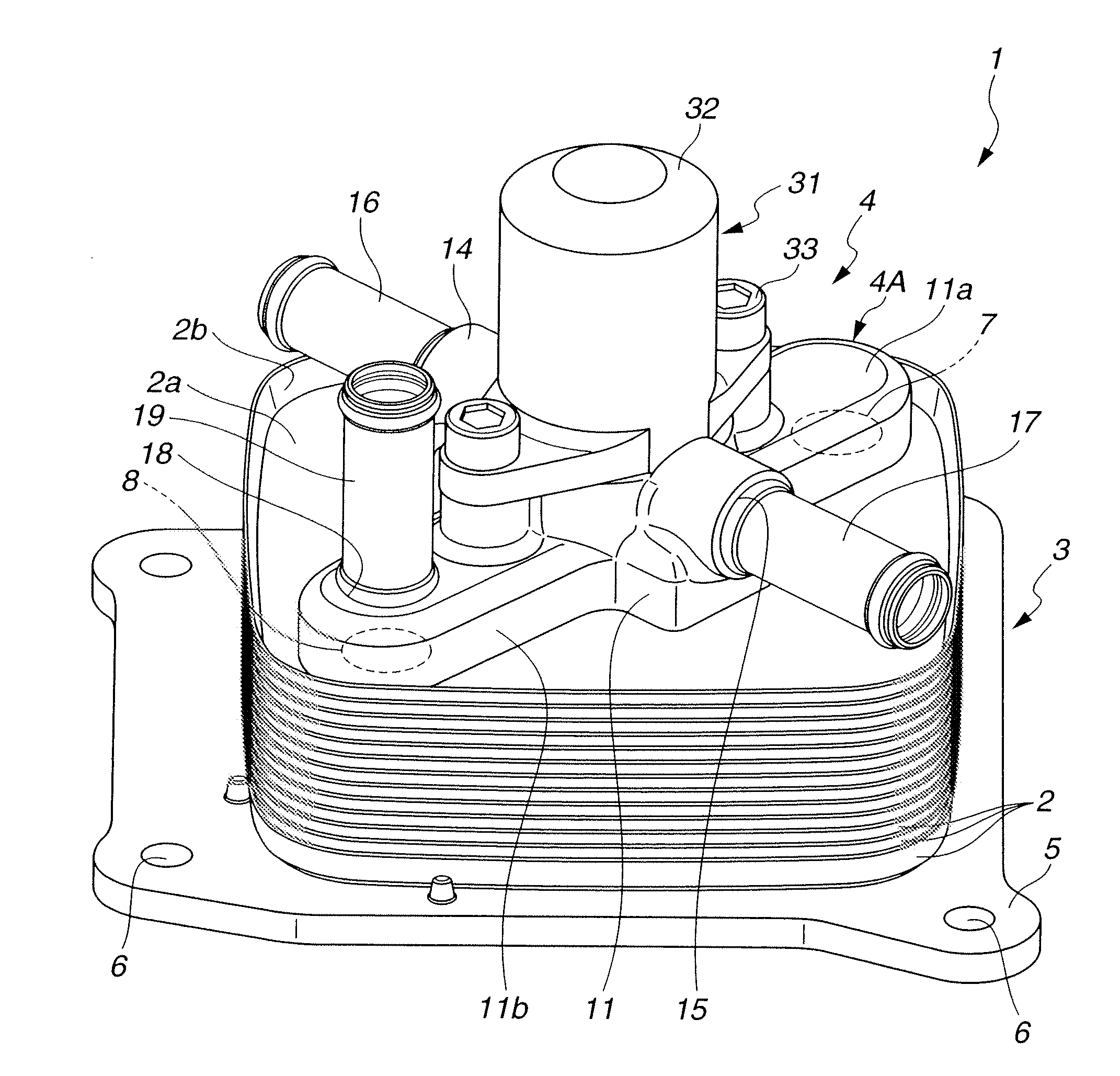
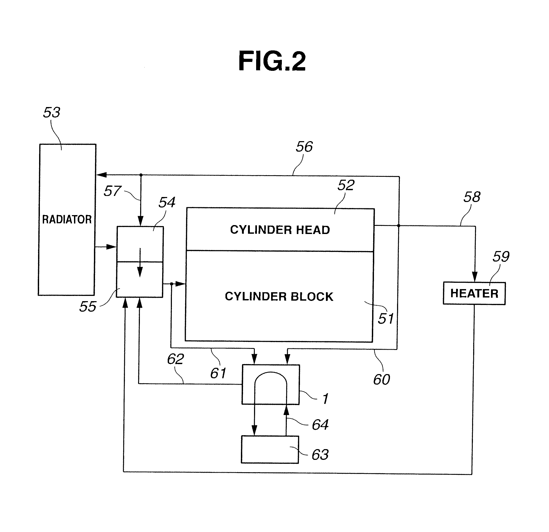
[0024]Referring now to FIG. 1 of drawings, an embodiment of an oil cooler according to the present invention is illustrated by the reference numeral 1. The oil cooler 1 in this embodiment is for cooling hydraulic oil of an automatic transmission of an automotive vehicle. The oil cooler 1 is used upon being incorporated in a cooling system for an internal combustion engine of the automotive vehicle as schematically illustrated in FIG. 2.

[0025]As shown in FIG. 2, the internal combustion engine is provided with a basic coolant circulation system which includes water jackets formed respectively in a cylinder block 51 and a cylinder head 52. A radiator 53 is fluidly connected to the water jackets. A thermostatic valve 54 is fluidly connected to the water jackets and the radiator 53. A water pump 55 is fluidly connectable to the water jackets and the radiator 53. Coolant whose temperature has become high upon receiving heat of various parts of the internal combustion engine is taken out f...


PUM


Abstract

An oil cooler includes a heat exchanger core having a plurality of plates laid one upon another to define each of an oil passage through which oil flows and a coolant passage through which coolant flows, between the plates. An uppermost plate of the plates has a core coolant inlet and a core coolant outlet. The core coolant inlet and the core coolant outlet are communicated with the coolant passage. A flow passage control valve is disposed on an uppermost part of the heat exchanger core and has a first coolant introduction opening through which coolant at a relatively high temperature is supplied and a second coolant introduction opening through which coolant at a relatively low temperature is supplied. The first coolant introduction opening and the second coolant introduction opening are changed over to be communicated with the core coolant inlet.

Description

BACKGROUND OF THE INVENTION[0001]This invention relates to an oil cooler to be used for cooling hydraulic oil of an automatic transmission of an automotive vehicle or lubricating oil of an internal combustion engine.[0002]For example, a temperature of hydraulic oil to be used in an automatic transmission of an automotive vehicle generally arises to a level higher than that of engine coolant of an internal combustion engine, during operation of the engine. The hydraulic oil is cooled by an oil cooler using the coolant, so that the temperature of the hydraulic oil can be maintained at its suitable level. In general, the oil cooler is installed, for example, on a housing of the automatic transmission, and the coolant is introduced from the side of the internal combustion engine to the oil cooler through outside pipings.[0003]Here, for example, during a cold starting of the internal combustion engine in winter season, it is desirable not to make a cooling action to the hydraulic oil by ...

Claims


Application Information

Patent Timeline
IPC IPC(8): F01P9/00
CPCF01M5/002F16H57/0417F28F2250/06F28D2021/0089F28F27/02F28D9/0031F28F9/0253
Inventor OHI, NAOKIARITA, ERIYA
Owner MAHLE FILTER SYST JAPAN CORP
Why Eureka
Try Eureka